YinYang Lamp
So here we have it the first LED design on my website.
Not my first actual design by any means but one I just installed and hence have fresh pictures of!
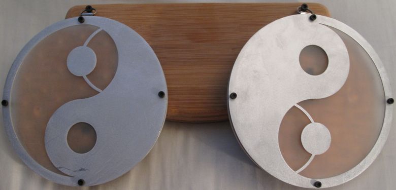
These were built as a friends birthday present/housewarming gift and were originally intended to be separate and wall hanging. As can seen above though, that didn't quite pan out. The lighting in the friends initial apartment was abysmal and needed an overhaul whereas the lighting in the second place was already pretty good. Also whereas in the first apartment the lights were to provide the majority of the illumination, in the second, they only really needed to provide some accent lighting.
The LEDs chosen were CREEs XH-G LEDs and are a reasonably powerful lighting class LED. As is typical of CREEs LEDs they come in a variety of specifications which helps makes the appropriate design of domestic lights a breeze. For a long time I have been unimpressed with the overall quality of light that CFLs and low CRI LEDs provide. As a result I take advantage of the higher CRI binned parts whenever I can. Of course this comes at an efficiency penalty but it's well worth it for the quality of light and atmosphere the right lighting can create in a room.
Each XH-G is a 1 watt device and I used the 90 CRI part with a warm white CCT of 2700K. Given the LEDs relatively high efficacy the 15 LEDs used in this design have the potential to put out a significant amount of light. When driven hard each lamp can put out in excess of 1000 lumens. This is a decent amount brighter than your typical 60 watt incandescent bulb, with both lamps putting out significantly more light than a single 100 watt.
The original power supply was going to be a laptop brick, split between the two lamps, so I had to come up with some sort of solution for driving the LEDs. As I was already familiar with the ZXLD1371 from Diodes Inc. this was the route I decided to go.
Not my first actual design by any means but one I just installed and hence have fresh pictures of!
These were built as a friends birthday present/housewarming gift and were originally intended to be separate and wall hanging. As can seen above though, that didn't quite pan out. The lighting in the friends initial apartment was abysmal and needed an overhaul whereas the lighting in the second place was already pretty good. Also whereas in the first apartment the lights were to provide the majority of the illumination, in the second, they only really needed to provide some accent lighting.
The LEDs chosen were CREEs XH-G LEDs and are a reasonably powerful lighting class LED. As is typical of CREEs LEDs they come in a variety of specifications which helps makes the appropriate design of domestic lights a breeze. For a long time I have been unimpressed with the overall quality of light that CFLs and low CRI LEDs provide. As a result I take advantage of the higher CRI binned parts whenever I can. Of course this comes at an efficiency penalty but it's well worth it for the quality of light and atmosphere the right lighting can create in a room.
Each XH-G is a 1 watt device and I used the 90 CRI part with a warm white CCT of 2700K. Given the LEDs relatively high efficacy the 15 LEDs used in this design have the potential to put out a significant amount of light. When driven hard each lamp can put out in excess of 1000 lumens. This is a decent amount brighter than your typical 60 watt incandescent bulb, with both lamps putting out significantly more light than a single 100 watt.
The original power supply was going to be a laptop brick, split between the two lamps, so I had to come up with some sort of solution for driving the LEDs. As I was already familiar with the ZXLD1371 from Diodes Inc. this was the route I decided to go.
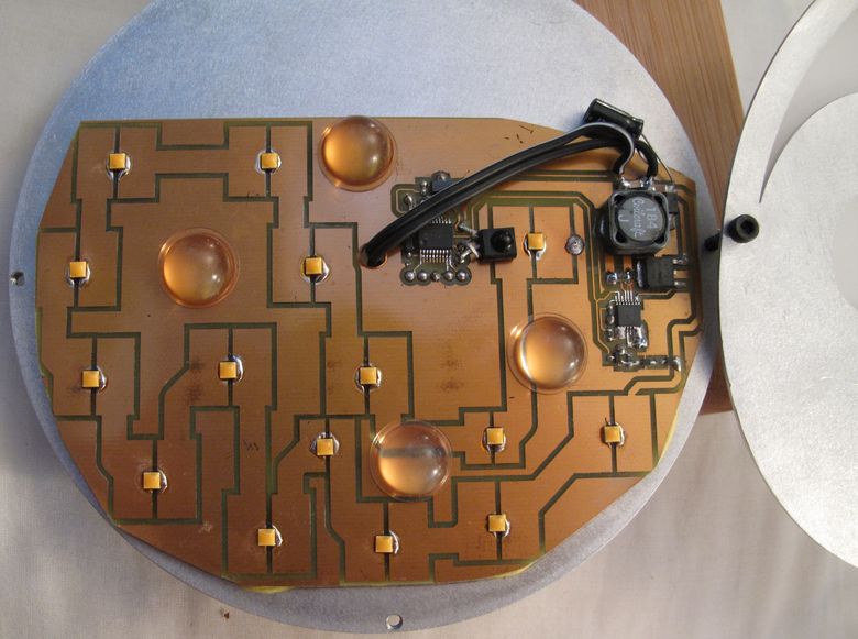
Above is a picture of the internals.
For heat dissipation and structural rigidity the PCB is glued to a backplate of aluminium. Both the front and backplate were designed in a CAD tool called Inkscape and then exported and sent off to a laser cutting fabrication house called lasermaster. This is a company I have used multiple times for more complex designs and they have always had resonable pricing and produced good results. A small window of perspex, sprayed with some glass frosting, was used as the main diffuser and mounted behind the cutouts on the front panel and the rubber feet were used as spacers to position the front plate in front of the back plate.
The LED driver is to the right hand side and is configured as a boost converter. The ZXLD1371 is a multi-topology device and can operate in whatever mode is necessary to provide whatever your target output voltage needs to be vs the voltage of your main power supply. The 15 series connected LEDs require around 50 volts for high current drive which is far and above the vast majority of off the shelf PSUs. Choosing a boost configuration is pretty standard in most cases like this.
To the left of the LED driver is a microcontroller. This allows the lamp to be dimmed using PWM and is operated via remote control. As the lights were originally intended to be rather bright, having control over the amount of light they put out was important. In the new location this was largely unnecessary, with the LEDs being operated at a much lower constant current.
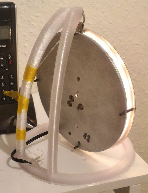
For the new apartment a wall mounting fixture was required as there were already holes in the wall. Holes for both securing a light in place and a recess that contained the required connectivity for wiring up a mains driven lamp. To this end I whipped up a shaped piece of wood, made of some layered bamboo lumber (LBL), I had lying around. A picture of the reverse side of this can be seen below.
For heat dissipation and structural rigidity the PCB is glued to a backplate of aluminium. Both the front and backplate were designed in a CAD tool called Inkscape and then exported and sent off to a laser cutting fabrication house called lasermaster. This is a company I have used multiple times for more complex designs and they have always had resonable pricing and produced good results. A small window of perspex, sprayed with some glass frosting, was used as the main diffuser and mounted behind the cutouts on the front panel and the rubber feet were used as spacers to position the front plate in front of the back plate.
The LED driver is to the right hand side and is configured as a boost converter. The ZXLD1371 is a multi-topology device and can operate in whatever mode is necessary to provide whatever your target output voltage needs to be vs the voltage of your main power supply. The 15 series connected LEDs require around 50 volts for high current drive which is far and above the vast majority of off the shelf PSUs. Choosing a boost configuration is pretty standard in most cases like this.
To the left of the LED driver is a microcontroller. This allows the lamp to be dimmed using PWM and is operated via remote control. As the lights were originally intended to be rather bright, having control over the amount of light they put out was important. In the new location this was largely unnecessary, with the LEDs being operated at a much lower constant current.
For the new apartment a wall mounting fixture was required as there were already holes in the wall. Holes for both securing a light in place and a recess that contained the required connectivity for wiring up a mains driven lamp. To this end I whipped up a shaped piece of wood, made of some layered bamboo lumber (LBL), I had lying around. A picture of the reverse side of this can be seen below.
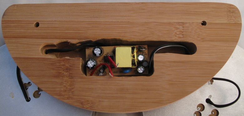
Two sheets of LBL were glued together to provide the required thickness, and the shape was created using a template along with a router. Recesses were then channeled into the backside of the LBL to accommodate a small SMPS and the necessary wiring. The SMPS was removed from a surplus wall wart. Safety with mains operated equipment is always extremely important, and although I have designed off-line devices I vastly prefer using an off the shelf unit for the initial line to DC conversion, plus vital isolation it provides.
So many basic LED replacement bulbs from China use hazardous stepdown techniques that have the potential to kill...I have no idea which engineers feel comfortable knowing that their products are lethal, but that's not a game I like to play at.
So many basic LED replacement bulbs from China use hazardous stepdown techniques that have the potential to kill...I have no idea which engineers feel comfortable knowing that their products are lethal, but that's not a game I like to play at.

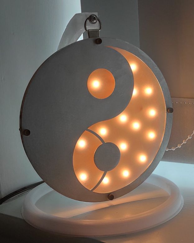
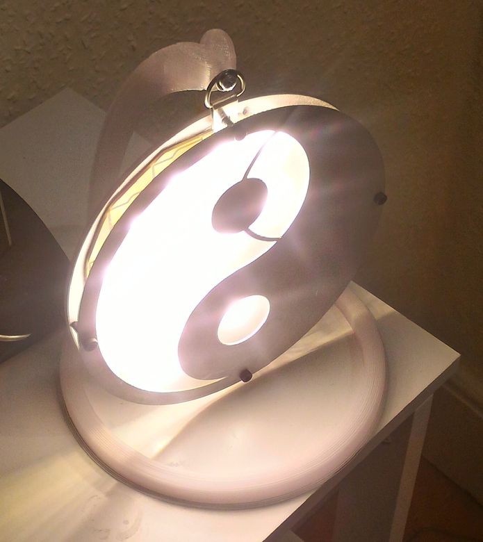
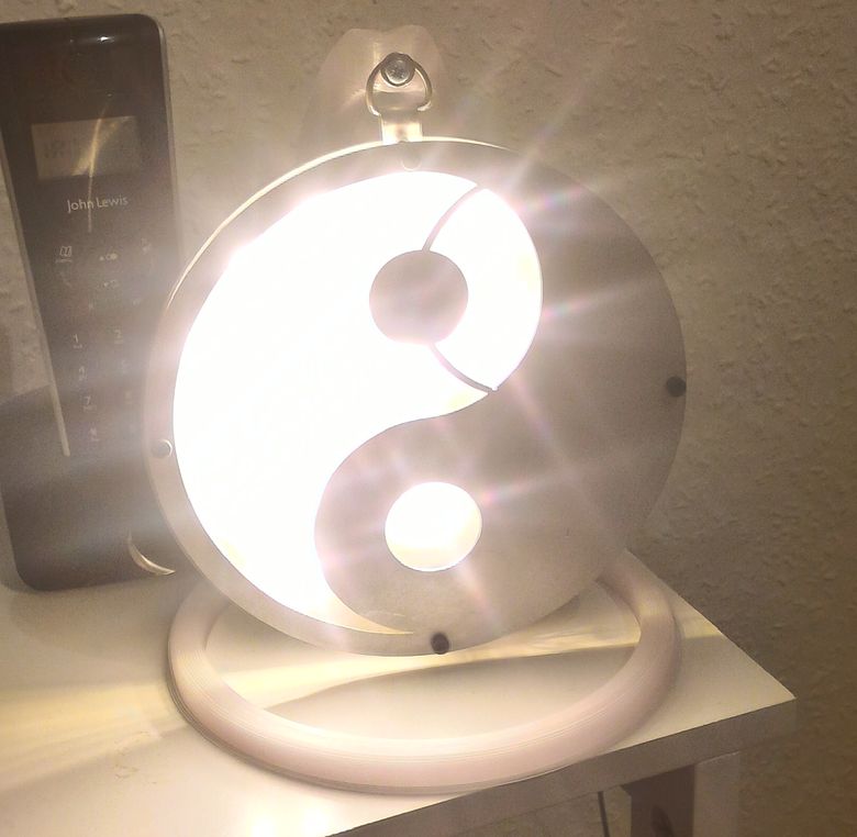
Taking pictures of lamps in operation is always a difficult task but surprisingly the camera on my mobile phone does a pretty decent job. Here are the lamps installed in their intended location and shot with my Nexus 5. The camera contains a built in high dynamic range mode of operation that was particularly useful here. The lamps cast a rather attractive halo out to the sides that help make them more than just lights in a room. Lighting doesn't just have to be functional it can be aesthetic too and this is something I've found significantly easier to accomplish when using LEDs as the light source.
Of course having made them originally I'm just happy that the lights are now in use again!
Of course having made them originally I'm just happy that the lights are now in use again!
Update!
My friend moved house and in his new apartment hanging something on the wall was impractical. As a result I came up with a 3D printed mount that would allow the lamps to hang but also so that they would sit on a desk or table. I also rewired them and added in a trigger to the onboard microcontroller's ADC that turned them into touch lamps.