Sushi Lamp
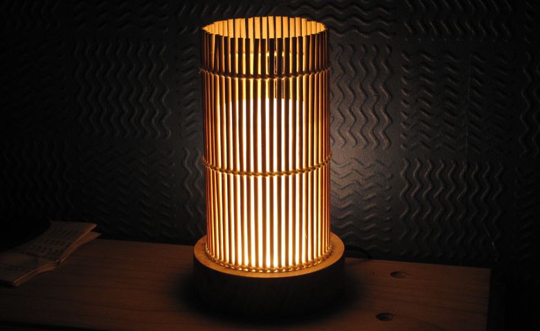
Here is a design that happened after a visit to a Japanese restaurant. Sometimes inspiration comes from funny places. Beneath the serving area the restaurant has a small shop, within which it sells various oriental bits and pieces related to serving food. This isn't the first time I've bought something from there with a project in mind but this time I noticed some sushi mats. I'm not entirely sure if these are supposed to be used for the preparation of the food or for the serving but that doesn't really matter, I thought they'd look great wrapped around some frosted perspex diffuser.
The idea behind these lamps was for something decorative and pleasant to look at. LEDs have a tendency to combine tiny size and high light output. While this is good from a general illumination point of view, it isn't so good for creating lights that are gentle on the eyes. While it's true that much the same can be said of traditional light bulbs, complete luminaires do tend to come with a lamp shade. The shade is there to basically shield your eyes from the bulb itself and to provide some control over where the light actually goes. With an LED lamp diffusers are typically used as a way of spreading the more directional light around, to integrate the light from what could possibly be multiple light sources/LEDs and to shield ones eyes from the direct glare of the LEDs themselves.
In this design a cylindrilcal diffuser is used to help accomplish these goals, as well as using multiple LEDs glowing dimly, rather than a couple glowing brightly. Make no mistake, LEDs are still quite expensive, but compared to 10 years ago they are pennies by comparison. Manufacturers like CREE have had a lot of success with their X-Lamp LED line and initially they focused on high power solutions of 3 watts and above. This is great for torches, car head lamps, halogen reflector type replacement bulbs and directional industrial lighting, but less useful for the domestic environment. Here omnidirectional light sources reign supreme with gentle, diffuse, illumination being preferred.
To this end there has been a more recent surge in LED manufacturers producing highly efficacious, lighting class LEDs in the 1/2 and 1 watt form factor. While LEDs of this power level have always been available what they've lacked is the tight quality control for colour temperature and CRI that the higher power variants have boasted, as well as their impressive efficacies.
This lamp has been designed around an operating point of around 2.5 watts, and while many of the single-die 3 watt LEDs would have sufficed, none of these would have given quite the same visual effect.
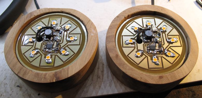
Above can be seen the internal construction of the lamp. Ever present is the flexible and cost effective ZXLD1371 LED driver from Diodes Inc. along with 8 LEDs. These are 1 watt parts and I could have quite easily used fewer but they are inexpensive. More LEDs means that each individual LED can operate at a lower drive current for a given light output. As an LEDs efficacy increases with decreasing current this also reduces the total system power. A lower overall system power means less heat needs to be dissipated, due to the systems ineffeciencies, and as LEDs get brighter with reducing temperature...You can see where this is going. There are many reasons for using more LEDs in a final design, but for this one it definitely helps with reducing glare.
Glare isn't the only thing that's improved as it also helps when it comes to perfecting the colour temperature of the light produced. These are LEDs from Lumileds 3535L HE line and these happen to come in a wide variety of colour temepratures and CRIs. A higher CRI results in better colour rendition in the objects that the light illuminates and the colour temperature defines how warm, or cool, the light is perceived to be. For most domestic illumination we want warm light, with the warm white standard usually being 2700K. I have always found 2700K to be a little on the 'cool' side for my tastes so it pleased me no end when I saw that the 3535L HE line also came in a 2200K binned part. As one would expect these are even warmer, a little too warm in fact, but when used in combination with some 2700K LEDs a perfect balance is acheived.
For this lamp I used four 2200K LEDs, with a CRI of 80, in combination with four 2700K LEDs with a CRI of 90. Whatever the end mixed result of this happens to be I do not know, but it certainly is very pleasing on the eye. Lumileds do posses a tool for calculating such things but I was unfortunately denied access...
Another thing worth mentioning is the copper area surrounding the LEDs. As you can see one of the pads that the LEDs are soldered too is quite enlarged and this is all to do with heat dissipation. Pretty much all high power LEDs have a separate pad included, usually on the underside of the package and it is used for getting rid of heat.
Above is an image that shows part of the top side copper layer of a PCB for using CREEs MK-R LED. As you can see you've got the two electrical contacts on either side of the package, but there is also a third, larger pad, in the middle. This third pad is basically a heat slug and needs to be connected in some way to a heat sink.
For DIYers this is a bit of a head scratcher.
The way that I've managed to get around this is to drill a hole (or two) in the centre of the third pad 1.5mm in diameter. I then insert some solid, silver plated, copper jewellers wire the same diameter as the hole and solder it in place. Obviously the top side of the wire has been sanded flat, but it is mounted flush with the pad and soldered into place via the reverse side copper. This gives a direct path for the heat to travel and with some additional sanding to the reverse side copper wire a way for the PCB to be interfaced with a heat sink.
This is a labour intensive process and isn't easy to pull off, especially with the smaller LED packages and it is not DIY friendly. High power LEDs are very susceptible to heat damage during the soldering process, so the last thing an inexperienced DIYer wants to do (it's not particularly appealing to an experienced one either!) is attempt a difficult soldering procedure, around an expensive LED part. Industry gets around this by using metal cored PCBs but we aren't so lucky.
If you need the high power density of something like an MK-R LED then there's not a lot you can do except buy a pre soldered LED. These come pre soldered to a MCPCB (sometimes called a 'star PCB') and take a lot of the headache out of using power LEDs, but these can be quite costly and you're obviously limited in the choice of LEDs. (Another option is to use a COB LED part. These are absolutely excellent if they fit your project type.)
Thankfully the newer ranges of 1 watt LEDs do away with the thermal slug and this makes using them an absolute breeze. The way in which these work is by connecting, what would be, the thermal slug, to one, or both, of the electrical contacts. The 3535L HE parts use the cathode, as indicated by the little notch in the corner of the plastic package. To this end all you have to do is enlarge the pad surrounding the cathode by a suitable amount and hey presto. The heat from the LED package is spread through the enlarged top-side copper pad and is then conducted through the substrate material of the PCB to the rear side copper. Now FR-4 fibreglass material may not be the most thermally conductive, but when the area is large and power density low enough, it works extremely well. CREE have a paper on this for use with their XH-G (and some others) LEDs and can be found on their website.
I have even used this method with some CREE XP-E LEDs, by tying the cathode to the thermal slug, and running them at lower power. These obviously require some soldering shinanigans as the contacts are completely concealed on the underside of the package, but the 3535L line has contacts that go up the side of the package so can be soldered entirely by hand - HURRAH!

For comparison's sake above is one of the pad configurations that I use for the 3535L HE LED. For DIYers, and the industry alike, this is great news as it allows very easy prototyping in combination with fabrication processes that have been long established (ie are inexpensive and accessible).
Moving on, here is the underside of the lamps showing the wooden base a little more clearly. One of the lamps required a switch so one was glued into place.
Moving on, here is the underside of the lamps showing the wooden base a little more clearly. One of the lamps required a switch so one was glued into place.
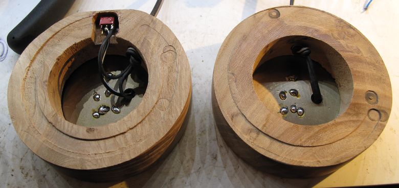
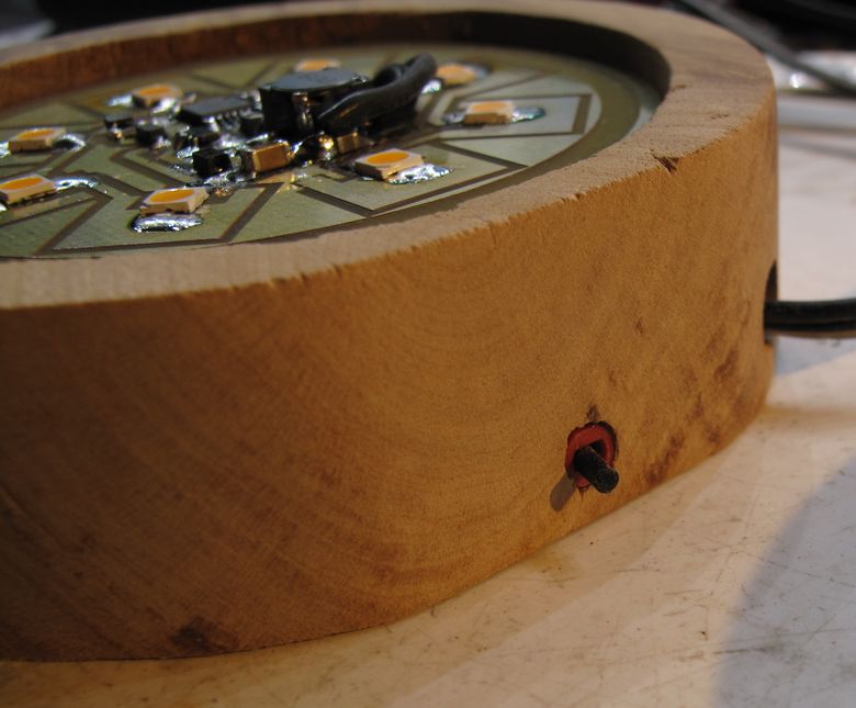
A closeup of the tiny toggle switch.
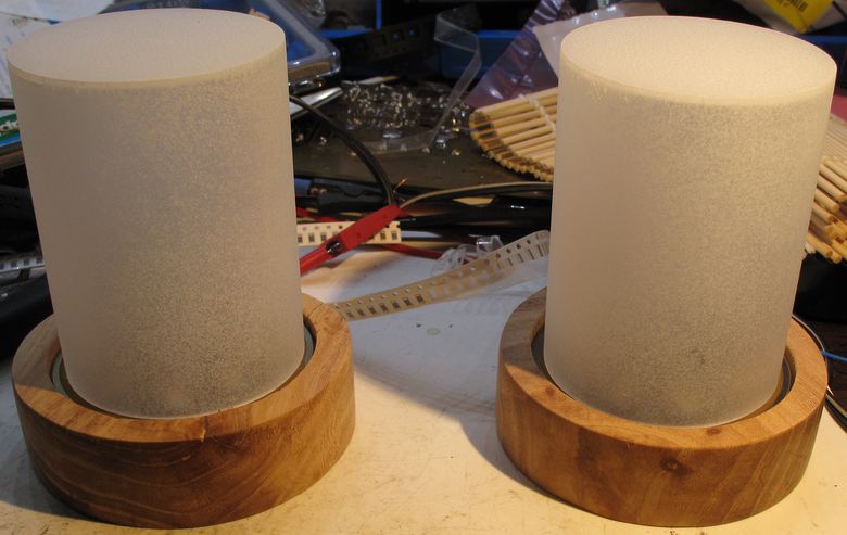
To act as a difuser and substrate for the sushi mat to wrap around, I used a cylinder of perspex along with a perspex top. These were then sprayed with a few layers of glass frosting in a can. The perspex was acquired via ebay.
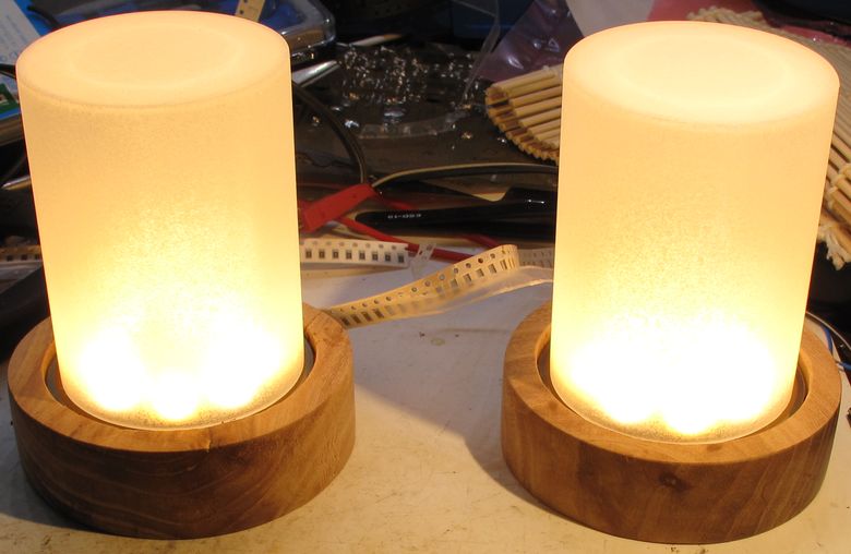
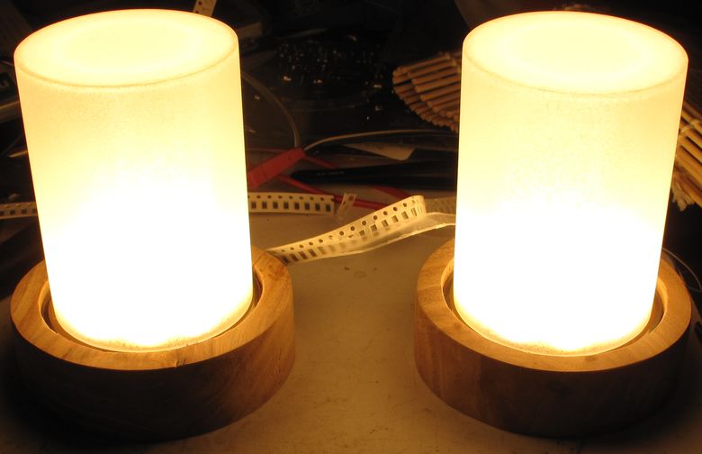
Here are two views of the lamps with different exposures showing the light and cylinder to good effect.
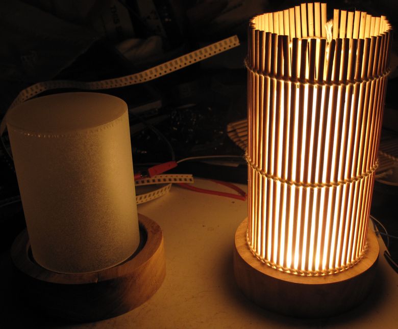
And now a sloppy wrap around with a sushi mat half falling off at the rear of the lamp. One nice aspect of the sushi mat is that it helps to block some of the light and breakup the light intensity even more.
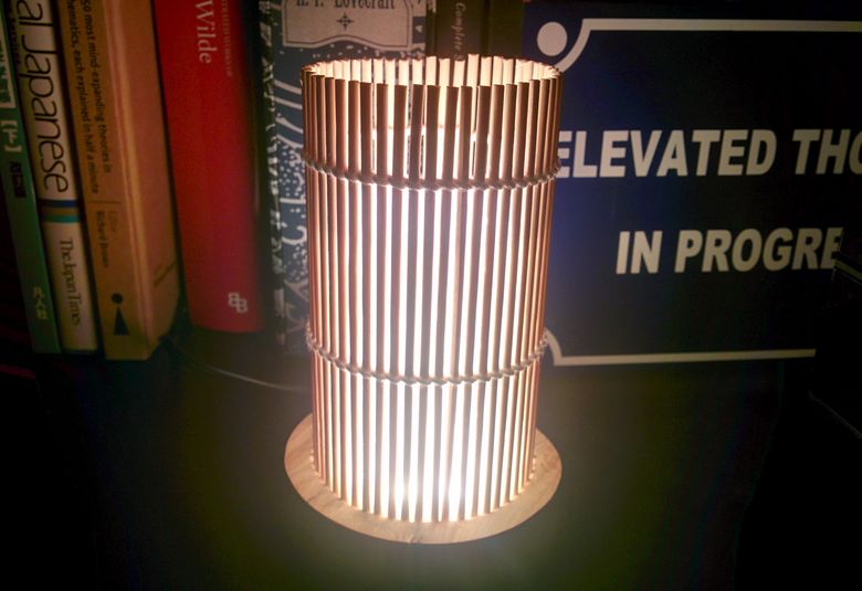
Above is the final shot, showing one of the two lamps in its final destination. On the shelf of a friends storage unit helping to provide some much needed light to a dark corner of a small room! It must be noted that it's quite difficult to capture the overall effect of the illumination on camera. The colour temperature is most accurately captured in the shots above the last one and the overall effect probably in the image at the top of the page.
One lamp was for myself and the other the aforementioned friend. We we both very pleased with the outcome!
One lamp was for myself and the other the aforementioned friend. We we both very pleased with the outcome!