High power offline LED driver and lighting system
Compared to my other LED designs this one is a little bit different. With my other designs, and mainly for convenience and safety, I have typically gone with a laptop brick or wall wart as the primary power supply. These tend to be compact and limited in their power output and for this application that would simply not do!
Previously my designs have been limited to around 20 watts and primarily for aesthetic reasons. It's a lot nicer to have several lamps in one room, rather than one super-bright lamp. But when one wants to bring a large amount of distributed illumination to a single space and all in one go (rather than a lamp at a time), something a little bit bigger is required.
The only practical way to achieve this is with an off-line, all in one solution. Low voltage and low current/lower power LED drivers are very common but these are not suitable for complete room installations approaching 100 watts. I had played with the AL9910 from Diodes Inc. but as this lacks isolation from the mains it's not the safest of options so roll on the LT3799.
The LT3799 is a very handy development from Linear Technology helping guys like me to realise an off-line high powered LED driver. The chip itself combines several necessary features for making this a success. The first is that it is powered directly from the mains. With low powered designs you can get away with using any ubiquitous PSU, but with high power solutions you need to look elsewhere. The second is that it includes active power factor correction. Again, with low power designs this isn't deemed necessary, but with high power designs maintaining a power factor close to 1 is required by law. And the third? Perhaps the most important from my point of view...the use of a transformer which performs the critical job of isolating the mains voltage from the output of the converter.
Transformers have always been the bane of my existance with regards to flirting with off-line solutions. You almost always have to wind your own, something I have no experience with. I have wound my own inductors for loudspeaker crossovers but a transformer is a completely different affair. This is especially so with transformers that are designed for resonant topologies where the transformers inductance, besides just the turns ratio, is also critical. Thankfully Linear Technology saw beyond this issue and collaborated with a number of magnetics companies and produced a series of off-the-shelf transformers for a wide variety of applications.
One of these happened to be a ~100 watt transformer from Wurth Elektronik that was designed to work with an output of around 90V at a current of 1 amp. I already owned a pair of CREE's CXA2011 LEDs so this was almost perfect. The CXAs could work with a maximum drive current of around 1 amp at a forward voltage of around 45V.
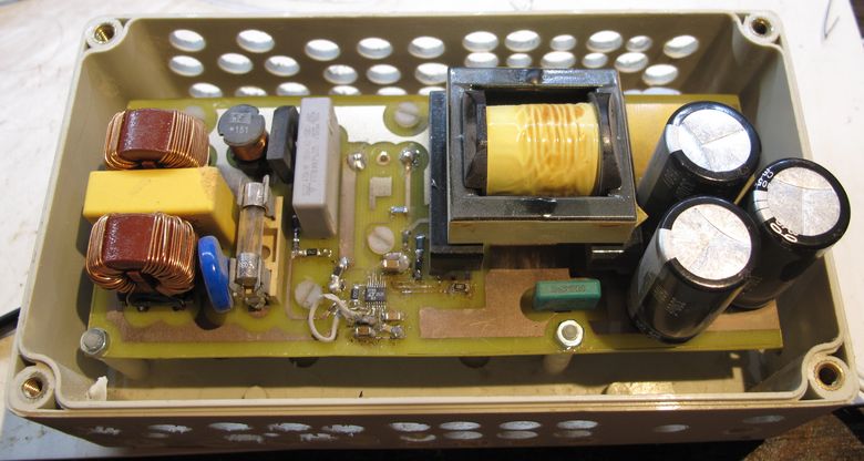
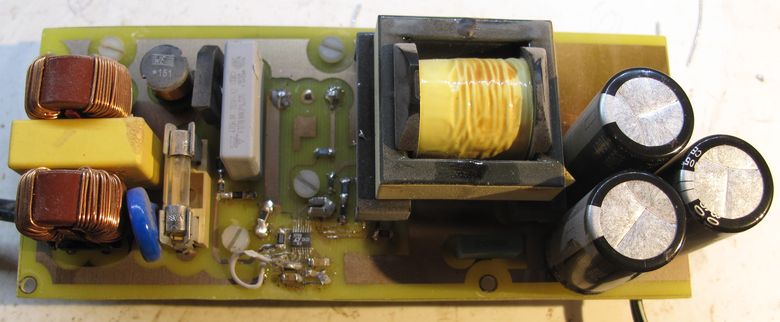
Design and layout of the PCB for the LT3799 wasn't particularly hard as all the parts are rather large. I did however have some initial problems with the currrent regulation. This caused the device to fall out of current regulation and either operate right up to the upper voltage cut off, or at a far higher current than intended. The problem was caused by noise interferring with the signal present to the control pins and some cap filtering helped to solve this.
Previously my designs have been limited to around 20 watts and primarily for aesthetic reasons. It's a lot nicer to have several lamps in one room, rather than one super-bright lamp. But when one wants to bring a large amount of distributed illumination to a single space and all in one go (rather than a lamp at a time), something a little bit bigger is required.
The only practical way to achieve this is with an off-line, all in one solution. Low voltage and low current/lower power LED drivers are very common but these are not suitable for complete room installations approaching 100 watts. I had played with the AL9910 from Diodes Inc. but as this lacks isolation from the mains it's not the safest of options so roll on the LT3799.
The LT3799 is a very handy development from Linear Technology helping guys like me to realise an off-line high powered LED driver. The chip itself combines several necessary features for making this a success. The first is that it is powered directly from the mains. With low powered designs you can get away with using any ubiquitous PSU, but with high power solutions you need to look elsewhere. The second is that it includes active power factor correction. Again, with low power designs this isn't deemed necessary, but with high power designs maintaining a power factor close to 1 is required by law. And the third? Perhaps the most important from my point of view...the use of a transformer which performs the critical job of isolating the mains voltage from the output of the converter.
Transformers have always been the bane of my existance with regards to flirting with off-line solutions. You almost always have to wind your own, something I have no experience with. I have wound my own inductors for loudspeaker crossovers but a transformer is a completely different affair. This is especially so with transformers that are designed for resonant topologies where the transformers inductance, besides just the turns ratio, is also critical. Thankfully Linear Technology saw beyond this issue and collaborated with a number of magnetics companies and produced a series of off-the-shelf transformers for a wide variety of applications.
One of these happened to be a ~100 watt transformer from Wurth Elektronik that was designed to work with an output of around 90V at a current of 1 amp. I already owned a pair of CREE's CXA2011 LEDs so this was almost perfect. The CXAs could work with a maximum drive current of around 1 amp at a forward voltage of around 45V.
Design and layout of the PCB for the LT3799 wasn't particularly hard as all the parts are rather large. I did however have some initial problems with the currrent regulation. This caused the device to fall out of current regulation and either operate right up to the upper voltage cut off, or at a far higher current than intended. The problem was caused by noise interferring with the signal present to the control pins and some cap filtering helped to solve this.
The relative efficiency of the unit is rather high (Linear quote 85-90% for various implementations) but 15% power losses for a 100 watt device is still 15 watts that need to be dissipated as heat. High temperature capacitors are a requirement in situations like this, the transformer is self contained but the output rectifiers and power MOSFET need to be kept suitably cool.
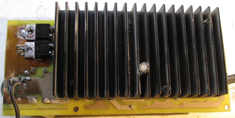
The picture above shows the rear side of the PCB. The large heatsink cools the main switch and is bolted securely, via tapped threads, to the PCB in several locations. The rectifier diodes are shown to the top left. Originally these were a single DPAK surface mount device that, on paper, should have offered reliable performance. Reality told a different story and after a couple of years use the unit failed on a particularly hot day in summer. The diode had failed short circuit. Not wanting the unit to fail again I beefed up the situation a little.
To store and mount the driver I bought a plastic Hammond enclosure from ebay and filled it full of holes.
To store and mount the driver I bought a plastic Hammond enclosure from ebay and filled it full of holes.
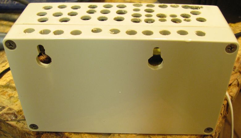
This is then hung on the wall, or rather to the backside of a support beam in the roof. The workshop is at the top of the mouse and mounting the unit to the beam keeps it well out of harms way.
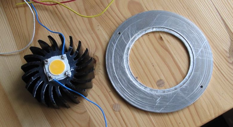
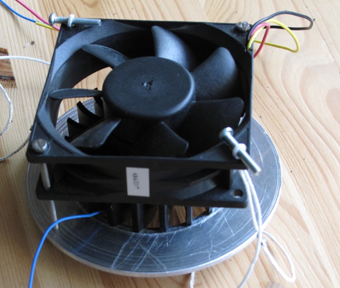
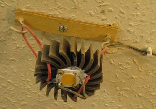
From a bit of experimentation it turned out that two point sources of light weren't sufficient to provide a distributed spread of illumination so two more were added for a total of four. Originally I had two of the CXAs suspended from the ceiling and fan cooled on two smallish heatsinks. This actually worked well and the fans were wired up in parallel with the LEDs with resistors added to set the fan speed. The fans didn't need to spin particularly fast but in a dusty environment fan cooling should really be avoided. Below can be seen how the LEDs were originally configured.
From a bit of experimentation it turned out that two point sources of light weren't sufficient to provide a distributed spread of illumination so two more were added for a total of four. Originally I had two of the CXAs suspended from the ceiling and fan cooled on two smallish heatsinks. This actually worked well and the fans were wired up in parallel with the LEDs with resistors added to set the fan speed. The fans didn't need to spin particularly fast but in a dusty environment fan cooling should really be avoided. Below can be seen how the LEDs were originally configured.
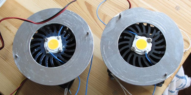
While there was nothing wrong with the above it didn't provide a large enough spread of light. Doubling up the number of LEDs helped significantly and wiring them in parallel with the original two resulted in much less thermal demand from the heatsinks. The fans could therefore be removed so the situation was a bit of a win-win, except of course for the added cost.
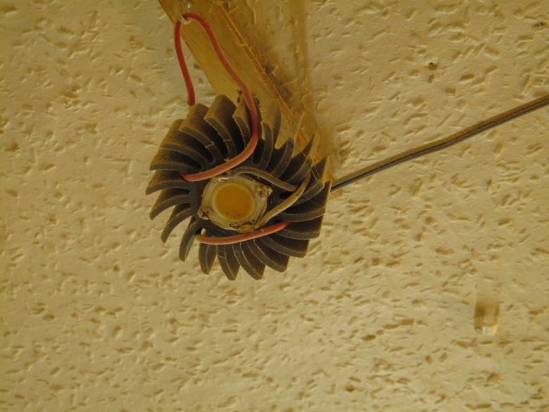
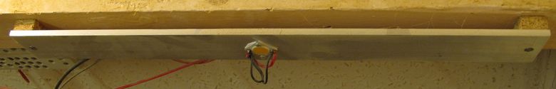
Above shows the two original CXAs in place but without the fan and heatsink assembly. The other two LEDs were mounted to bars of aluminium as is shown below.
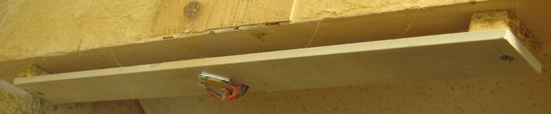
The two bars were mounted to the aforementioned support beam and the driver and box, plus all of its drilled holes, can be seen to the left of the first aluminium bar mounted LED. Bits of wood were used to separate the bar from the beam to help keep things cool.
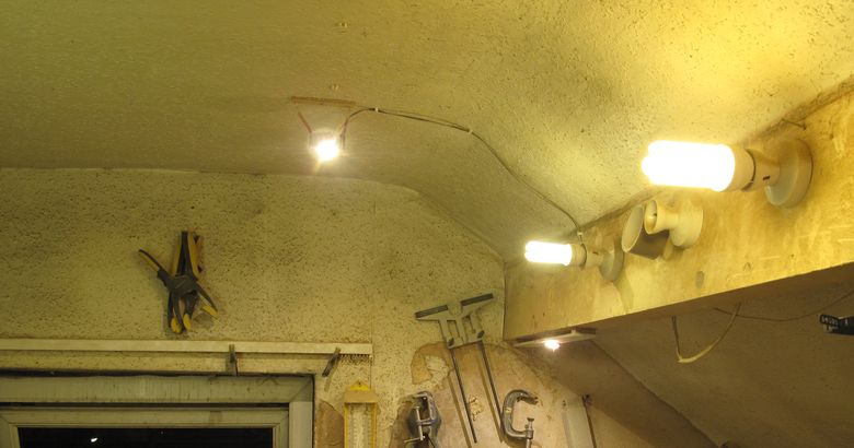
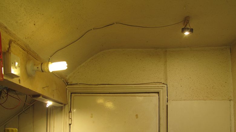
The tlights in operation.
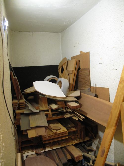
The two beam mounted LEDs actually sit above the main working area so help dramatically in providing enough light. The final part to the system was to add in some illumination for the side room, the door to which can be seen in the above picture next to the main door to the workshop.
This was a bit of an after thought but as I had the PCB and LEDs lying around from another project I figured it made sense to put it to good use. These LEDs had been wired up for 1 amp nominal and as this system was running at ~800mA it was easy enough to wire it up in series with the CXAs.
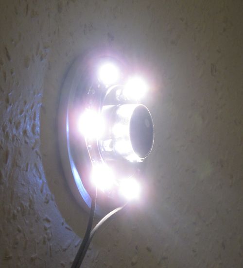
These were some old CREE CLN6A LEDs. A very old LED as LEDs go and very expensive compared to the current generation of 1 watt LEDs but there was certainly nothing wrong with them so I hung them on the wall and voilà!
Since installing the system I have considered redoing the main LEDs and opting for a completely different strategy. As mentioned prices have fallen dramatically in the last few years for LEDs. There are much more attractive options available these days that would also provide an even better spread of light. Most notably Lumileds have released their LUXEON 3535L HE and HE plus lines. These are 1 watt nominal devices that come in a vast range of CCT and CRI options and best of all, cost about £0.15 each. In comparison I paid £1.78 per CLN6A back in late 2010, so that's progress for you!
Three of the 3535Ls in parallel would suit the 800mA of regulated current, four could be used if I wanted some margin of safety, which wouldn't be a bad idea considering the price.
I have used these LEDs before and they are excellent. They have a relatively low forward voltage too of 3V. For the ~90V forward drop of the four series/parallel CXA2011s I'd need 30 series connected 3535Ls. If I placed 4 in parallel, per small PCB, I'd need 120 LEDs and that would still cost less than two CXAs cost originally. It would also provide 30 seperate light sources for a very even distribution of light throughout the entire work area. This is why LEDs are the future!