Ebike controller
The fact that his has ended up being my first electronics project is a bit of a surprise. Besides LED lighting, my main focus has always been on audio electronics. More than anything though I'm probably just lazy in that I haven't got around to writing up any of my audio projects yet!
I suffer from Chronic Fatigue Syndrome as well as intense motion sickness. This makes public transport quite troublesome and with the CFS, walking long distances, running or cycling quite difficult. I have always enjoyed cycling, and having been a fan of Robert Llewellyn's Fully Charged Youtube channel, it occurred to me that you could probably buy conversion kits for ebikes and indeed, you can, so I purchased a kit from wooshbikes. This was the GSM 18A kit with a built in controller and is a mid-drive kit. This means that the motor turns the pedals and thus powers the bike via the standard gearing. Wheel hub motors drive the wheel directly and therefore work with a fixed gear ratio. This makes them less flexible in terms of going up hills and limits efficiency across a wide range of travelling speeds.
The GSM kit has been fantastic but over time I realised I want more, both in terms of motor control and how the pedal assistance works. The Bafang/8FUN conversion kits come with the ability to be reprogrammed and I originally thought of changing to one of those, but then I thought, why don't I go about building my own?
The GSM 18A kit also comes in two variaties. One with the controller and one without, the one without makes adding your own controller extremely easy and is also less expensive. The only issue with this would be, how exactly would I go about this?
Pretty obviously the heart of an electric vehicle is the motor controller and the motor itself. Brushless DC motors, such as is used here, do not naturally commutate and requiring pretty sophisitcated control electronics in order to spin. These can be fairly crude, such as is used in simple PC fans, or fairly complex, using powerful DSPs. DSP solutions have only really come on within the last few years though as processor efficiency and power have improved. Before then a real-time, DSP, solutions was impractical, but these days that is not the case, which is fantastic for the small EV sector.
Having researched some of the alternatives one of the best solutions turned out to be TIs Instaspin controllers, with their field orientation control (FOC) system for sine wave driven brushless motors.
So what is field orientated control?
Motors work due to the attractive and repulsive combinations of magnetic fields and as a motor spins these fields need to be constantly realigned in order to keep the motor spinning. If these fields aren't aligned properly then a motor will, at best, lose efficiency, or at its worst stop spinning altogether. Brushed DC motors control the alignment of these magnetic fields via a mechanical commutator. The position of the armature (the spinning part), relative to the stator (stationary part), is automatically handled by the brushes and commutator. As the motor turns the commutator controls which phases of the motor windings are energised and which are not. Brushless motors do not have this luxury and require different approaches to commutation.
The simplest of these is via hall effect sensors. These detect magntic fields and when imbedded within parts of the stator provide positional data for the armature. A controller can then use this positional data to time the energising of the motor phases and provide effective commutation. Given their simplicity there is actually nothing wrong with this method but it does have some limitations. The first is long term reliability. If any of the hall sensors fail, or if they should slip out of alignment, then the control of the motor becomes compromised. The second limitation is simply to do with the basic alignment of the hall sensors to begin with. Any misalignment will result in compromised commutation and thus affect the performance of the motor.
There's are very good reasons though why the small motors used for quad copters etc, do not use hall effect sensors. Quads are prone to crashing and any disloding of the hall sensors would render a motor, and the quad, useless. Then there's the matter of weight, complexity and the extremely high speeds that these motors are expected to work at. The larger, and usually slower, of the RC motors sometimes come with hall sensors, but almost all of them do not.
The way that these motors commutate is via a control method known as field orientated control. During normal operation two phases of a brushless DC motor are driven, whilst the third is not. During the off period of the disconnected phase the back EMF generated can be measured, and used, as a way of detecting the armature position, and thus, provide a way of commutating the motor.
Field oriented control systems are not all equal mind you. Some are quite complex and some relatively simple. To detect the back EMF current sense resistors are necessary, BLDC motors typically have three phases and you can use one, two or three current sense resistors in a FOC system. More is obviously better but the code processing the back EMF data can also vary considerably. Then there's the voltage measurements that you can include for the motor phases for additional control.
TIs Instaspin FOC system uses up to three current shunts whilst also monitoring the voltage of each motor phase. In additional to this TIs control system measures the back EMF continuously over the period of disconnection, then integrates it, providing extremely accurate positional data for commutation. Integrating the back EMF helps significantly with motor performance when the motor is operating at low speeds.This is one of the main drawbacks to FOC systems. When the motor isn't spinning zero back EMF is being generated, so they can have issues with starting up. This is especially true when needing to startup under load. Also, the slower a motor spins, the smaller the instantaneous back EMF is, making commutation harder. The total amount of energy however, per rotation of the disconnected phase, remains exaxctly the same, it's just that the amount of time per rotation goes up. This is where integration comes in. If you were to simply rely on the magnitude of the back EMF you'd have trouble at lower speeds, but if you integrate the EMF measurement you use the area under the curve for commutation, rather than the magnitude of the points drawing the curve. The area under the curve is exactly the same regardless of the speed that the motor is spinning so accurate commutation can be had both at low and high speeds.
The small motors for aviation do not suffer when using less sophisitcated control schemes because they are never required to deliver power at startup. Propellers typically provide extremely low resistance when spinning slowly, and during normal operation, they are rotating at very high speeds.
TIs Instapin FOC solution made a lot of sense in terms of my application so I decided it would be worth giving a go.
For an ebike though, the motor controller is only half of the story. While it is true you could add a simple throttle to the motor controller and be done with it, there's far more to a modern ebike than that. From a safety point of view an ebike generally requires switched brakes so that the motor unit is disengaged when you pull them. You'd figure that you'd release the throttle before applying the brakes, but in an emergency situation, with sudden breaking, you need the motor unit to shut off immediately, rather than when you choose to leg go of a throttle. Then there's the possibility of a throttle failure. The brake cut off being essential in regaining control of the vehicle. Safety asside, constantly having to operate a throttle is a bit tiresome and one of the reasons for having an ebike is so that you can at least get some exercise. Any decent ebike motor unit/conversion kit will include a set of sensors designed for detecting pedal motion, which can then be decoded and used to switch the motor unit on and off.
Then, as well as basic functionality, some kind of display is always nice. Everyone likes to know how fast they are going, or how far they've gone, but in the case of ebikes, there's a whole lot more you may wish to know. Firstly some sort of indicator for the charge level of the battery is a good idea. Just as you can drive a car to be more economic, the same is true for ebikes. If you're getting low on energy those are the times when you need to maximise efficiency. Another useful thing to know is how much power you are using. With a power readout you can take an active role in learning how to reduce the amount of power you are using, thus helping to maximise battery life in the event that you need to go further than usual, or you get into a situation where you cannot recharge your battery.
In the case of my ebike I use a continuously variable transmission from Nuvinci. These are fantastic for use with ebikes and they have a sweet spot for maximum efficiency in terns of energy transfer to the wheel. This happens at a ratio of 1 to 1. That is, one revolution on the input of the transmission, equals one revolution on the output of the transmission. Either side of parity the efficiency drops off, so knowing what ratio you're at is important.
The same is true for the motor unit itself, most electric motors operate most efficiently when running at high speed and in terms of mechanically commutated motors the speed of the motor (compared to its unloaded speed) is relative to the amount of power it is delivering. In the case of BLDC motors, where feedback is used, this isn't quite the case as the speed of the motor remains constant until a predetermined current limit is reached. Still, when you reach this limit the motor slows down and efficiency drops. Having a readout that lets you know when the motor slows down, relative to the desired rotational speed, is useful because it lets you know when you should shift down when climbing a hill.
The ability to drive a decent display, along with all the additional inputs, requires more than the Instaspin DSP can provide. As a result, an additional micro controller was chosen as a way of interfacing with the rest of the bikes inputs and peripherals. The motor controller works by performing, high speed, real time measurements, performing real time arithmetic and then sending real time control data to the MOSFET drivers. Commutation and timing is handled via precisely timed interrupts and if you add too much to the DSPs load it'll choke and fail to operate the motor. While adding to the DSPs main while loop could be done without too many consequences, adding to the interrupts would be a recipe for disaster. To function currectly all of the features, outside of the motor control, require interrupts to operate properly too, so a secondary processor makes a lot of sense. Given my familiarity with the PIC24 range of 16 bit processors from Microchip, I decided to go with the flagship, a PIC24E with 512k of program memory. Indeed it turns out that this was a good idea as a lot of its features and internal memory was utilised.
Going up to a 32 bit processor would be the next step and would certainly provide more scope for fancy graphics, but is otherwise unnecessary. Microchip have a new line of 32 bit processors coming out, the PIC32MK. These would be perfect as a replacement, giving more than is necessary for the project, but also making more sense too. The 32 bit architecture makes for far more efficient data storage when concerning the large data arrays for the display and would allow for more elabourate graphics. The 32 bit MK processors also include a dedicated floating point calculation unit which would be quite useful when concerning the calculations for speed, distance and time. To compensate for this numbers have to be scaled up for accurate computation such that numbers beyond the decimal point are moved ahead of it. The 32 bit MK processors include many more timers, which would be handy and finally they also come with a small amount of on-board EEPROM. Remembering certain parameters after switch off, is necessary for a project like this, such as to remember how far you have gone etc. This requires the use of a small amount of non volatile memory and while the standard flash memory, common to microcontrollers, can be used as such, it is very inefficient. Flash memory sectors can only be written a small number of times before expiring. To circumvent this EEPROM can be used, as it can be written many more times, but in the case of the PIC24E series, a separate memory chip is required. With the PIC32MK it is not, thus saving board space and potentially costing less, as the PIC32MK range is expected to be priced similarly.
So first up we have the display head unit.
I suffer from Chronic Fatigue Syndrome as well as intense motion sickness. This makes public transport quite troublesome and with the CFS, walking long distances, running or cycling quite difficult. I have always enjoyed cycling, and having been a fan of Robert Llewellyn's Fully Charged Youtube channel, it occurred to me that you could probably buy conversion kits for ebikes and indeed, you can, so I purchased a kit from wooshbikes. This was the GSM 18A kit with a built in controller and is a mid-drive kit. This means that the motor turns the pedals and thus powers the bike via the standard gearing. Wheel hub motors drive the wheel directly and therefore work with a fixed gear ratio. This makes them less flexible in terms of going up hills and limits efficiency across a wide range of travelling speeds.
The GSM kit has been fantastic but over time I realised I want more, both in terms of motor control and how the pedal assistance works. The Bafang/8FUN conversion kits come with the ability to be reprogrammed and I originally thought of changing to one of those, but then I thought, why don't I go about building my own?
The GSM 18A kit also comes in two variaties. One with the controller and one without, the one without makes adding your own controller extremely easy and is also less expensive. The only issue with this would be, how exactly would I go about this?
Pretty obviously the heart of an electric vehicle is the motor controller and the motor itself. Brushless DC motors, such as is used here, do not naturally commutate and requiring pretty sophisitcated control electronics in order to spin. These can be fairly crude, such as is used in simple PC fans, or fairly complex, using powerful DSPs. DSP solutions have only really come on within the last few years though as processor efficiency and power have improved. Before then a real-time, DSP, solutions was impractical, but these days that is not the case, which is fantastic for the small EV sector.
Having researched some of the alternatives one of the best solutions turned out to be TIs Instaspin controllers, with their field orientation control (FOC) system for sine wave driven brushless motors.
So what is field orientated control?
Motors work due to the attractive and repulsive combinations of magnetic fields and as a motor spins these fields need to be constantly realigned in order to keep the motor spinning. If these fields aren't aligned properly then a motor will, at best, lose efficiency, or at its worst stop spinning altogether. Brushed DC motors control the alignment of these magnetic fields via a mechanical commutator. The position of the armature (the spinning part), relative to the stator (stationary part), is automatically handled by the brushes and commutator. As the motor turns the commutator controls which phases of the motor windings are energised and which are not. Brushless motors do not have this luxury and require different approaches to commutation.
The simplest of these is via hall effect sensors. These detect magntic fields and when imbedded within parts of the stator provide positional data for the armature. A controller can then use this positional data to time the energising of the motor phases and provide effective commutation. Given their simplicity there is actually nothing wrong with this method but it does have some limitations. The first is long term reliability. If any of the hall sensors fail, or if they should slip out of alignment, then the control of the motor becomes compromised. The second limitation is simply to do with the basic alignment of the hall sensors to begin with. Any misalignment will result in compromised commutation and thus affect the performance of the motor.
There's are very good reasons though why the small motors used for quad copters etc, do not use hall effect sensors. Quads are prone to crashing and any disloding of the hall sensors would render a motor, and the quad, useless. Then there's the matter of weight, complexity and the extremely high speeds that these motors are expected to work at. The larger, and usually slower, of the RC motors sometimes come with hall sensors, but almost all of them do not.
The way that these motors commutate is via a control method known as field orientated control. During normal operation two phases of a brushless DC motor are driven, whilst the third is not. During the off period of the disconnected phase the back EMF generated can be measured, and used, as a way of detecting the armature position, and thus, provide a way of commutating the motor.
Field oriented control systems are not all equal mind you. Some are quite complex and some relatively simple. To detect the back EMF current sense resistors are necessary, BLDC motors typically have three phases and you can use one, two or three current sense resistors in a FOC system. More is obviously better but the code processing the back EMF data can also vary considerably. Then there's the voltage measurements that you can include for the motor phases for additional control.
TIs Instaspin FOC system uses up to three current shunts whilst also monitoring the voltage of each motor phase. In additional to this TIs control system measures the back EMF continuously over the period of disconnection, then integrates it, providing extremely accurate positional data for commutation. Integrating the back EMF helps significantly with motor performance when the motor is operating at low speeds.This is one of the main drawbacks to FOC systems. When the motor isn't spinning zero back EMF is being generated, so they can have issues with starting up. This is especially true when needing to startup under load. Also, the slower a motor spins, the smaller the instantaneous back EMF is, making commutation harder. The total amount of energy however, per rotation of the disconnected phase, remains exaxctly the same, it's just that the amount of time per rotation goes up. This is where integration comes in. If you were to simply rely on the magnitude of the back EMF you'd have trouble at lower speeds, but if you integrate the EMF measurement you use the area under the curve for commutation, rather than the magnitude of the points drawing the curve. The area under the curve is exactly the same regardless of the speed that the motor is spinning so accurate commutation can be had both at low and high speeds.
The small motors for aviation do not suffer when using less sophisitcated control schemes because they are never required to deliver power at startup. Propellers typically provide extremely low resistance when spinning slowly, and during normal operation, they are rotating at very high speeds.
TIs Instapin FOC solution made a lot of sense in terms of my application so I decided it would be worth giving a go.
For an ebike though, the motor controller is only half of the story. While it is true you could add a simple throttle to the motor controller and be done with it, there's far more to a modern ebike than that. From a safety point of view an ebike generally requires switched brakes so that the motor unit is disengaged when you pull them. You'd figure that you'd release the throttle before applying the brakes, but in an emergency situation, with sudden breaking, you need the motor unit to shut off immediately, rather than when you choose to leg go of a throttle. Then there's the possibility of a throttle failure. The brake cut off being essential in regaining control of the vehicle. Safety asside, constantly having to operate a throttle is a bit tiresome and one of the reasons for having an ebike is so that you can at least get some exercise. Any decent ebike motor unit/conversion kit will include a set of sensors designed for detecting pedal motion, which can then be decoded and used to switch the motor unit on and off.
Then, as well as basic functionality, some kind of display is always nice. Everyone likes to know how fast they are going, or how far they've gone, but in the case of ebikes, there's a whole lot more you may wish to know. Firstly some sort of indicator for the charge level of the battery is a good idea. Just as you can drive a car to be more economic, the same is true for ebikes. If you're getting low on energy those are the times when you need to maximise efficiency. Another useful thing to know is how much power you are using. With a power readout you can take an active role in learning how to reduce the amount of power you are using, thus helping to maximise battery life in the event that you need to go further than usual, or you get into a situation where you cannot recharge your battery.
In the case of my ebike I use a continuously variable transmission from Nuvinci. These are fantastic for use with ebikes and they have a sweet spot for maximum efficiency in terns of energy transfer to the wheel. This happens at a ratio of 1 to 1. That is, one revolution on the input of the transmission, equals one revolution on the output of the transmission. Either side of parity the efficiency drops off, so knowing what ratio you're at is important.
The same is true for the motor unit itself, most electric motors operate most efficiently when running at high speed and in terms of mechanically commutated motors the speed of the motor (compared to its unloaded speed) is relative to the amount of power it is delivering. In the case of BLDC motors, where feedback is used, this isn't quite the case as the speed of the motor remains constant until a predetermined current limit is reached. Still, when you reach this limit the motor slows down and efficiency drops. Having a readout that lets you know when the motor slows down, relative to the desired rotational speed, is useful because it lets you know when you should shift down when climbing a hill.
The ability to drive a decent display, along with all the additional inputs, requires more than the Instaspin DSP can provide. As a result, an additional micro controller was chosen as a way of interfacing with the rest of the bikes inputs and peripherals. The motor controller works by performing, high speed, real time measurements, performing real time arithmetic and then sending real time control data to the MOSFET drivers. Commutation and timing is handled via precisely timed interrupts and if you add too much to the DSPs load it'll choke and fail to operate the motor. While adding to the DSPs main while loop could be done without too many consequences, adding to the interrupts would be a recipe for disaster. To function currectly all of the features, outside of the motor control, require interrupts to operate properly too, so a secondary processor makes a lot of sense. Given my familiarity with the PIC24 range of 16 bit processors from Microchip, I decided to go with the flagship, a PIC24E with 512k of program memory. Indeed it turns out that this was a good idea as a lot of its features and internal memory was utilised.
Going up to a 32 bit processor would be the next step and would certainly provide more scope for fancy graphics, but is otherwise unnecessary. Microchip have a new line of 32 bit processors coming out, the PIC32MK. These would be perfect as a replacement, giving more than is necessary for the project, but also making more sense too. The 32 bit architecture makes for far more efficient data storage when concerning the large data arrays for the display and would allow for more elabourate graphics. The 32 bit MK processors also include a dedicated floating point calculation unit which would be quite useful when concerning the calculations for speed, distance and time. To compensate for this numbers have to be scaled up for accurate computation such that numbers beyond the decimal point are moved ahead of it. The 32 bit MK processors include many more timers, which would be handy and finally they also come with a small amount of on-board EEPROM. Remembering certain parameters after switch off, is necessary for a project like this, such as to remember how far you have gone etc. This requires the use of a small amount of non volatile memory and while the standard flash memory, common to microcontrollers, can be used as such, it is very inefficient. Flash memory sectors can only be written a small number of times before expiring. To circumvent this EEPROM can be used, as it can be written many more times, but in the case of the PIC24E series, a separate memory chip is required. With the PIC32MK it is not, thus saving board space and potentially costing less, as the PIC32MK range is expected to be priced similarly.
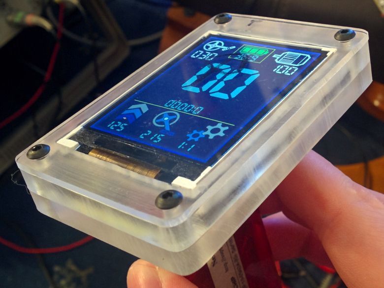
So first up we have the display head unit.
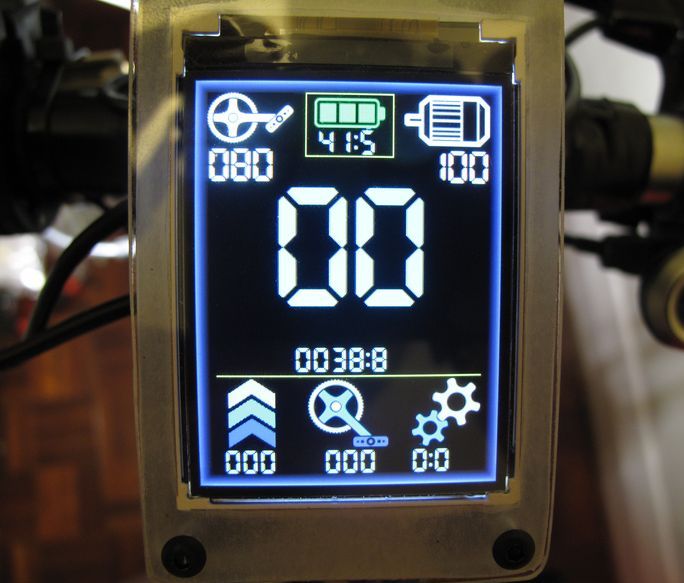
To the top left is the desired cadence that the motor unit will assist up to, to the middle the voltage level of the battery and to the right the desired amount of power the motor will assist with. Currently the variable power feature doesn't work. The Instaspin motor control software isn't really designed for altering the current limit on the fly. Various parameters that affect motor performance and controller stability are based on the value of the current limit and as a result the maximum current is integrated more heavily into the control structure. This isn't a particularly big issue but if you really wanted to maximise efficiency you could bring down the current limit so that acceleration would be limited as would your maximum speed. I guess this is one of the draw backs of TIs FOC implementation, but there's always room for improvement!
The large figures below the above are used to show how fast you are going and with the small figures, below the speed, showing how far you have travelled. The distance can be toggled to show either the total distance the bike unit has gone, or your current journey distance and is resettable on command. Both of these figures are currently in km.
Towards the bottom are three additional parameters, useful for varying the way you cycle in an effort to go further per charge. The chevrons to the left show the input power to the motor controller, not counting for efficiency losses within the inverter itself. I could have chosen to display the actual output power of the motor but this is less useful. When you know how much power is being drawn from the battery pack you can estimate how long you can keep cycling before running out of energy. This can then allow you to alter your riding style in an effort to go further, if required.
The crank icon to the middle shows the cadence that the motor unit is actually maintaining. Ideally the desired and actual cadence should be equal, if they are not, you should really think about lowering the gear you are in. Then finally the two cog wheels to the right represent the gear ratio that the Nuvinci hub is maintaining. For maximum efficiency this should read 1.0. In my case this corresponds to a speed of around 25kph. If I wished to raise or lower this value then changing the size of the sprocket on the back wheel would be the way to go.
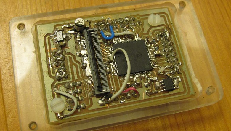
Internally things look like this. Not very exciting, it's essentially the PIC24, a connector for the displays FPC, an EEPROM, seen in the SOIC package, and a 3.3V voltage regulator. As can be seen the unit itself is constructed out of layered clear perspex. Given the prototype nature of this project some wires were needed as the projects requirements changed!
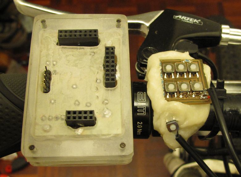
To the reverse of the display can be seen an array of connectors. There are quite a few redundant pins here and some are doubled up to help with connector integrity. Why all the connectors? Because where I live one needs the ability to remove the display, lest some idiot try and steel it. To the right of the display can be seen some buttons. These are IP67 rated, so are completely weather proof, and provide the means by which the settings of the ebike are altered. The buttons themselves have been press fit into a blob of mouldable plastic that sits next to the left handlebar. Two buttons alter the cadence up and down, two should theoretically alter the current limit of the motor controller and one swaps between total distance and the resettable journey distance. A long press on this button will reset the journey distance. The sixth button doesn't do anything as of yet, but could easily swap between miles and kilometers.
In addition to the 6 control buttons is a button for your thumb that activates the motor and regulates it to the desired cadence. My previous ebike had a throttle, which was completely pointless, either you want the motor on at your desired cadence, or off. I also found that the protruding lever of the throttle tended to get pushed by accident. Inadvertantly causing the motor to spring into life. Not so much a problem if you are aware that it can happen, but when others had given the bike a test ride it had taken them quite by surprise. Of course we are talking about a '250 watt' ebike here. If this were a 1000 watt model, or more, as some are, the throttle could be a death trap. You certainly don't want to turn the motor on by mistake with one of those!
In addition to the 6 control buttons is a button for your thumb that activates the motor and regulates it to the desired cadence. My previous ebike had a throttle, which was completely pointless, either you want the motor on at your desired cadence, or off. I also found that the protruding lever of the throttle tended to get pushed by accident. Inadvertantly causing the motor to spring into life. Not so much a problem if you are aware that it can happen, but when others had given the bike a test ride it had taken them quite by surprise. Of course we are talking about a '250 watt' ebike here. If this were a 1000 watt model, or more, as some are, the throttle could be a death trap. You certainly don't want to turn the motor on by mistake with one of those!
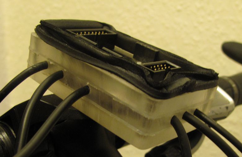
And here can be seen the side of the display that mounts to the bike frame directly. The IDC connectors are pretty solid and given the number of pins used hold the display in place rather snugly. As can be seen a layer of foam sealer is used between the two to protect against the ingress of rain water. Here you can also see the layered perspex construction in greater detail, along with the thin layer of silicone rubber between the layers, again, to keep out water.
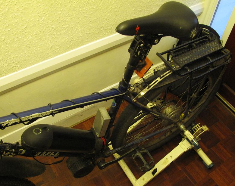
Above is a a shot of the rear of the bike that highlights the next important details. The black cylindrical object is the battery. This contains 40 18650 cells, wired in 4 parallel, 10 series connected strings.This provides a float voltage of 42V and a theoretical cut-off of 25V for the cell chemistry used. In practice though the battery management system cuts this off at 28V, which is a very good idea considering cell balancing and the fact that the cells can deliver next to no current below around 3V anyway.
To use a RC-hobby term, the kv rating of the motor would far better suit a higher bus voltage. As it stands when a comfortable cadence of 80RPM is set the system becomes incapable of maintaining this at anything other than close to a full charge. Given how the battery voltage sags during normal use you find that your riding performance is quite modulated by the fluctuating battery voltage. This is less than ideal and rather irritating. If a nominal '48V, 13 series cell' battery pack were to be used then this would not be an issue.
To help relieve the irritation of the performance being modulated by the battery voltage, both in terms of overall charge level and instantaneous sag, I actually installed a boost converter into the base of the batter module. Obviously this isn't ideal when it comes to maximising the distance you can travel, but a lot of care was taken in keeping the boost converter high efficiency. To this end I chose a polyphase boost converter from Linear Technology and using Linear's design tools, heavily optimised the design for excellent theoretical efficiency(98-99%+) . Indeed the unit remains suitably cool even under rather significant loading, which is important for battery longevity as much as it is preserving the distance you can travel. When the battery voltage dips below 33 volts the boost converter disengages. Doing so provides a significant drop in overall performance but also servers as a great way of indicating that the battery is getting low on charge. When this happens you can easily go a decent distance, but only if you ride efficiently!
At some point I may rewire the battery pack for 13 series connected cells with 3 parallel strings. Using 39 of the 40 cells.
The short black cylinder sticking forwards of the bottom bracket is the motor unit and you can see a close-up of this below.
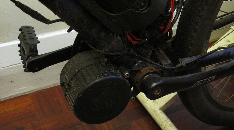
In the standard GSM 18A kit with controller, the motor controller is installed within the motor unit. I intend to do exactly the same thing once my design has been finalised but for the time being the motor controller is inside the silvery, aluminium, box fastened above the battery.
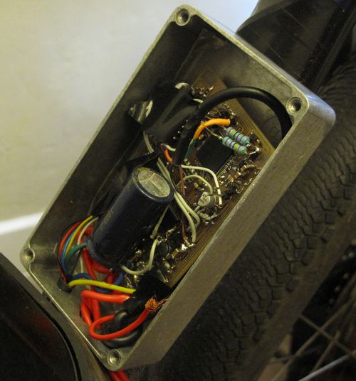
Here can be seen the aluminium case with the lid off.
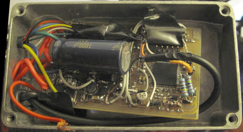
And here an image showing slightly more detail.
To the right can be seen the TMS320 DSP from TI that does all of the heavy lifting. To the left of this is the DRV8301 MOSFET driver and then to the far left are the power electronics. To aid in efficiency a lowish switching frequency of 15kHz was chosen. This is only suitable due to the relatively high inductance of the motor but it does allow for MOSFETs, with relatively high gate charges, without sacrificing much light load efficiency. This helps because the MOSFET parameters can then be optimised around minimising conduction losses. Here I am using 6 relatively small, surface mount FETs with an RDSon of ~ 0.0012ohms and along with the similarly small 0.001ohm current shunts, helps to keep the overall conducted, IR losses, very low and overall system efficiency high. Importantly the small amount of heat generated also helps to improve system reliability.
For communication between the display unit and the motor driver I had originally chosen the CAN bus. This uses a two wire, low impedance, balanced tramission and also includes some error correction. This makes it perfect for noisy environments such as this, where EMI generated from the motor could intefere with signal integrity. Unfortunately I didn't realise that the CAN bus required seperate tranceivers along side the DSP and micro controllers so I was forced to swap to the I2C protocol. This is definitely not what anyone would choose to use, it's relatively high impedance, offers no instrinsic error correction and uses a nominally 'on' state as its resting state. Still one works with what they've got and I found that it actually worked. I slowed down the I2C bus to work at around 60kHz and also installed I2C buffers to help things along. These buffers are extremely simple and come in a very small package but have the benefit of being able to work with low value pull up resistors, so help keep the line impedance low. Suffice it to say that using the I2C protocol, along with low impedance buffers, works surprisingly well. The simplicity of these I2C buffers meant that they could be squeezed into the current project on tiny PCBs, whereas the CAN bus parts may not have.
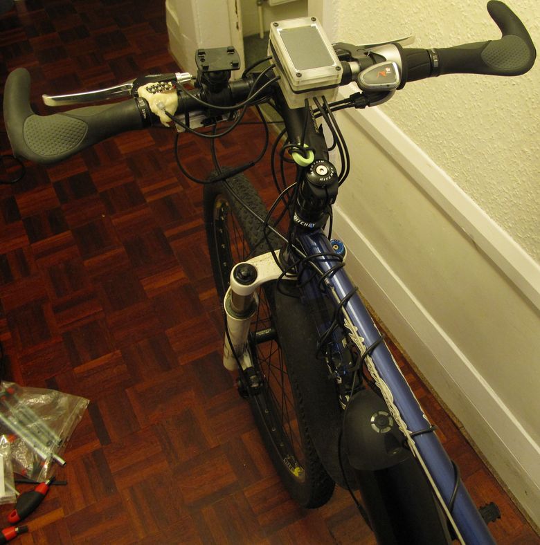
Here is a shot of the front of the bike, the ferrite ring can likely be removed, but it was put in place when I was debugging noise out of the system that was inteferring with the operation of the micro controller in the head unit. RC filters were needed on all of the micros inputs to prevent false triggering. This is the first time I've really worked on a system that produces high amounts of EMI and it was certainly a big learning experience!