Ebike MkII
Since the previous design many years have passed and with those years many changes have also come about. However after working for all that time the prototype motor driver suffered from a series of failures. The failures were isolated to a partially failed solder joint with one of the power MOSFETs. Thermal cycling of the power stage was found to be the root cause. Given all the modifications that I had made to the controller, and all the times the PCB had been worked on, it was time for an upgrade. Serviceability of the original design was horrendous and to that end the new design would focus heavily on improving this.
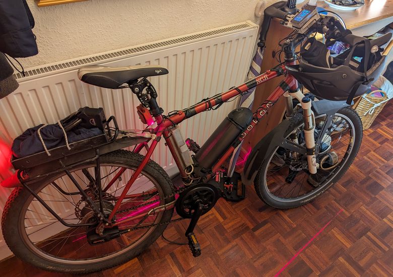
Aside from the electronics the bike itself had undergone a series of changes but the most relevant was an upgraded frame. As the bike's drive train uses a single speed chain connection the previous mountain bike frame, with vertical rear drop-outs, required a chain tensioner to function correctly. Single speed designs usually have horizontally orientated rear drop-outs. These allow you to move the position of the back wheel towards, or away from, the front chain ring and thus tension the chain. The new frame, a Wanga from the manufacturer Voodoo, came with sliding rear drop outs for tensioning the chain, so bye bye chain tensioner. I would expect this to improve efficiency ever so slightly as less moving parts is always a good thing but the biggest improvement was the reduction in noise. The new frame also came with a geometry more suited to the front suspension forks.
Aside from the frame upgrade there were a couple of issues with the previous design that needed improving upon and in no particular order these were.
1) A change to the battery for higher voltage operation eliminating the boost converter.
2) A rewinding of the motors stator to raise its Kv rating.
3) A significant lighting system for increased visibility and safety.
The first was an obvious change as it would improve efficiency and give more range. Not to mention give greater headroom and allow the motor to spin at higher speeds. To this effect I bought a bunch of NCR18650PF cells and constructed a 13S-3P, 48V, battery. Along with a Bluetooth battery management system for easy diagnostics of the battery pack should it ever misbehave. The previous battery had been a 10S-4P configuration, so the new one was 1 cell less in total capacity, but the new pack ended up providing a nice improvement in overall range.
With the new battery in place it turned out that the RPM at the front chain-ring worked best at around 100 RPM. While I wasn't going to pedal that quickly this resulted in a sweet spot for efficiency and the gear ratio of the NuVinci N360. The trouble with this was that the motor system could only maintain 100 RPM with the battery voltage above about 50% charge. I figured the best solution to this would be to rewind the stator of the motor and decrease the winding count. This would lower the back EMF generated and increase the Kv rating. It was also a chance to, potentially, increase the amount of copper within the stator slots and decrease copper losses. This was unlikely to do anything particularly beneficial though as the new motor would require more current to run than the old one. Then as luck would have it I actually had a roll of enamelled copper wire sitting on a shelf with just the right gauge for the rewinding.
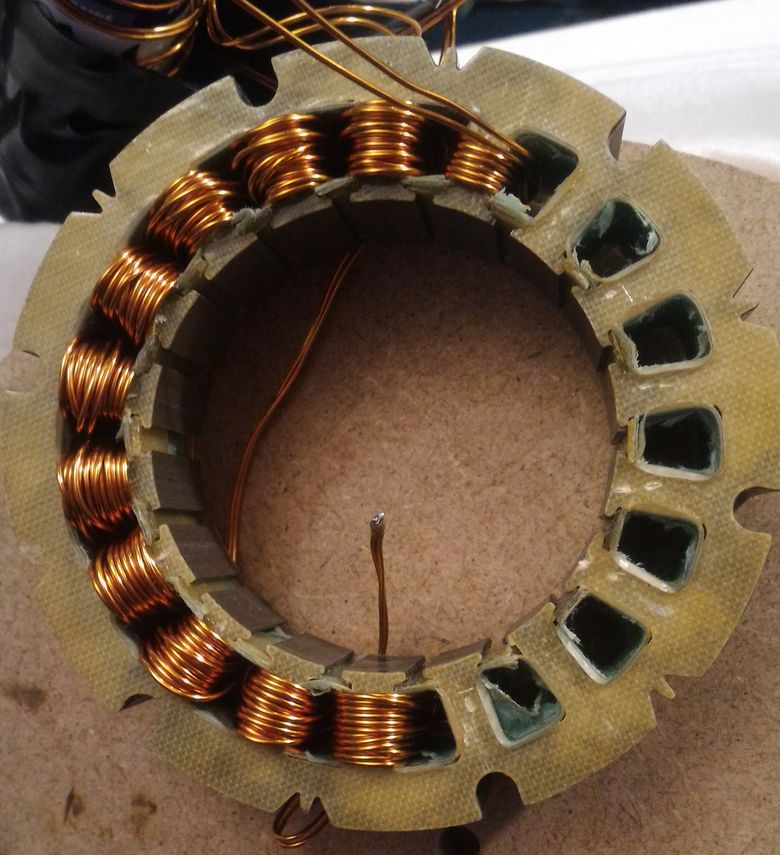
Above is a picture of the stator during the rewinding process. This took days to accomplish and I wouldn't recommend anyone do this if they have the choice. Maybe for a tiny RC motor but not something bigger. It's also extremely hard on the hands so expect them to get sore.
Below is a picture of the finished stator complete with being soaked and baked in a polyester resin.
Below is a picture of the finished stator complete with being soaked and baked in a polyester resin.
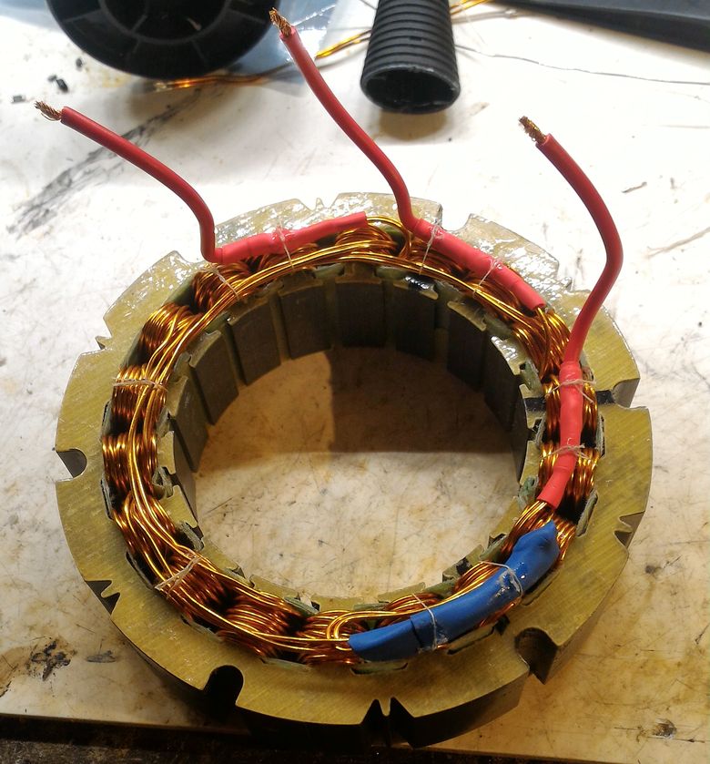
The new stator did the trick and the bike was then able to maintain 100RPM even with the battery at its lowest state of charge.
For the third point I wanted to go with a design that would leave nothing wanting. This included daylight running, indicators, a modulated rear light to indicate braking, and a switchable system to give better lights at night.
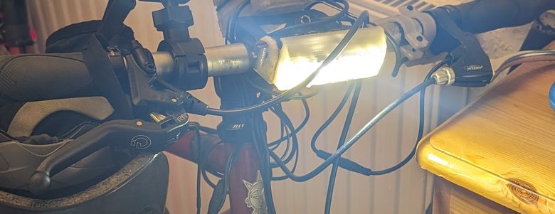
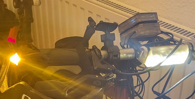
The front lights ended up using a combination of MK-R and XHP35 high intensity LEDs from CREE. I tried my hand at making a MCPCB of my own for them and it went fairly well. The LEDs then have their light focused via asymmetric, wall washing, lenses from LEDiL to concentrate their light towards the road. The front light is switched so that half of the lights are turned off during the day. A 3D printed shroud is used to protect them from the rain. In addition, when the front light is switched onto maximum, there are two red laser diodes that come on and project lines down the side of the bike. I saw the idea for this on some advert and bought a cheap eBay light with the supposed laser lines. Much to my disappointment they were so dull as to be almost invisible. Well in the true DIY spirit of things I purchased some decent laser diode replacements and recycled the optics from the eBay lamp. This worked extremely well and you can see one of the red lines, to the side of the bike, in the image at the top of the page.
Below is a picture of the front light.
For the third point I wanted to go with a design that would leave nothing wanting. This included daylight running, indicators, a modulated rear light to indicate braking, and a switchable system to give better lights at night.
The front lights ended up using a combination of MK-R and XHP35 high intensity LEDs from CREE. I tried my hand at making a MCPCB of my own for them and it went fairly well. The LEDs then have their light focused via asymmetric, wall washing, lenses from LEDiL to concentrate their light towards the road. The front light is switched so that half of the lights are turned off during the day. A 3D printed shroud is used to protect them from the rain. In addition, when the front light is switched onto maximum, there are two red laser diodes that come on and project lines down the side of the bike. I saw the idea for this on some advert and bought a cheap eBay light with the supposed laser lines. Much to my disappointment they were so dull as to be almost invisible. Well in the true DIY spirit of things I purchased some decent laser diode replacements and recycled the optics from the eBay lamp. This worked extremely well and you can see one of the red lines, to the side of the bike, in the image at the top of the page.
Below is a picture of the front light.
The rear lights followed a similar concept as the front ones using 4 cree XP-E LEDs and 4 narrow angle lenses, again from LEDiL. As the power density around the rear LEDs was much less than the front lights a MCPCB was not necessary. With a little creative PCB design the heat generated is spread over the surface copper. Under normal operation the rear LEDs are PWM dimmed to 25% their maximum output. When the brakes are pulled the duty cycle is increase to 100%.
Below is a picture of the rear lights.
Below is a picture of the rear lights.
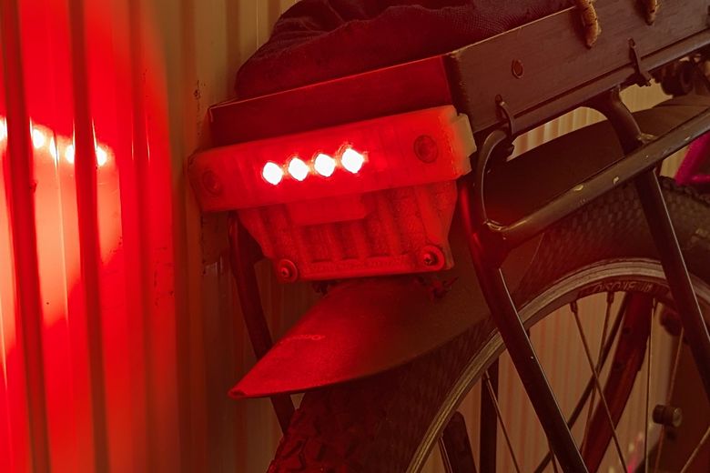
As can be seen there are two additional lenses to the sides of the 3D printed housing. These are the rear indicator lights and they use more XP-E LEDs but in the PC amber variant. These, like white LEDs, use a blue main LED but then use a phosphor coating to create the desired colour. This offers significant improvements in efficiency, and brightness, but widens the spectral peak of the target colour.
The indicator lights at the front of the bike use the same XP-E LEDs but this time a side focusing lens from Carclo optics. The indicators are inserted into the ends of the handlebars and the lenses make sure that most of the light goes ahead and behind.
Below can be seen the handlebar indicator.
The indicator lights at the front of the bike use the same XP-E LEDs but this time a side focusing lens from Carclo optics. The indicators are inserted into the ends of the handlebars and the lenses make sure that most of the light goes ahead and behind.
Below can be seen the handlebar indicator.
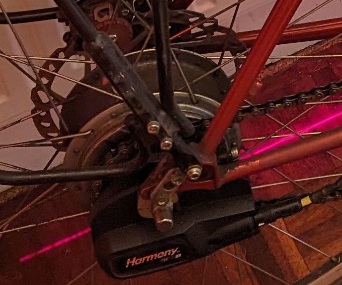
Besides what I've already described one other feature was added to the bike. The NuVinci continuously variable transmission, on the rear wheel, is usually adjusted, much like lots of bike gear systems, via a twist grip on the handle bars. If you want to play with something a little more fancy, however, NuVinci offer an electronic shifting system. Even more sophisticated is an electronic shifting system that is supposed to integrate with Bosch Ebikes. This is called the Harmony system and the idea is that it works to maintain a constant RPM at the front chain ring. If it gets too hard/easy to pedal, and the RPM changes as a result, then the Harmony automatically adjusts the gear ratio to compensate.
Well the Bosch/NuVinci system uses the CAN bus to communicate and I tried contacting NuVinci for details on this but they were not forthcoming. As a result I opened up the Harmony shifter, removed all the electronics, and wired the shifter motor, plus a hall sensor used as positional feedback, to the external connector. I then designed a motor driver circuit, for a standard brushed motor, and wired it up to the I2C interface that was already in place.
I then programmed the display control unit to adjust the gear ratio based off of the Ebikes motor RPM. This took a considerable amount of fine tuning, to prevent oscillation, but the final result works really well.
Below can be seen the Harmony unit.
Finally comes the remake of the main Ebike motor driver. Here is a picture comparing the previous design to the new one.
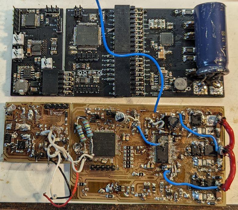
It doesn't take a genius to work out which is which!
The small PCB, tacked on to the top-left of the bottom PCB, is the motor driver for the Harmony shifter system and uses a DRV8801 along with a LM5013, in the new design, and a LM5160A in the old one.
As can be seen I took a very modular approach to the redesign. I wanted to make servicing as easy as possible so each functional unit was separated out to its own PCB. The board on the left makes up the motor driver for the Harmony shifter. The board in the middle has the TMS320F28054F that's responsible for implementing the sensor-less field orientation control for the Ebike motor and the PCB on the right has the power electronics for driving the Ebike motor.
In the redesign I also changed the DRV8301 MOSFET driver to one of Texas Instruments more modern smart drivers. Here I chose to go with the DRV8353FH. A hardware controlled device with 3 current shunt amplifiers. Ideally I had wanted to go with a DRV that integrated a buck driver as well but this was the only 100V capable part available at the time as I did this during the chip shortage.
The wonderful thing about the smart drivers is that they automatically sense the switching state of the output MOSFETs and then insert the required amount of dead-time necessary to ensure safe switching. This completely eliminates the potential for any cross-conduction but also keeps the dead-time inserted to the absolute minimum. Excessive dead-time distorts the sinusoidal waveform driving the motor, increases noise, and increases torque ripple. My guess is that it would also lower efficiency somewhat too.
To ensure the highest reliability I chose to go with 4 layer PCBs in the redesign and had them fabricated. Besides enabling better PCB layouts a 4 layer PCB also has better potential for thermal conductivity so should reduce the effects of the thermal cycling.
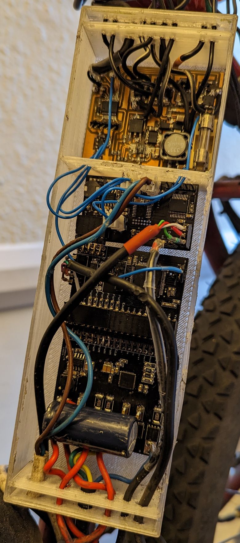
Above is the redesigned system installed on the bike in its 3D printed box. The PCB right at the top is the LED driver system for the lighting and uses a LT3756 in SEPIC configuration with coupled inductor.