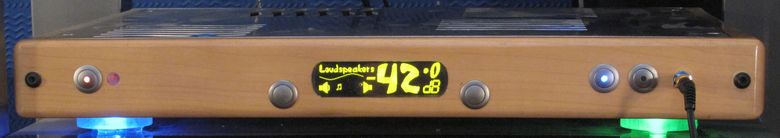
Pre-amplifier/DSP/Active crossover
A few years ago the DCX2496, from Behringer, seemed to be all the rage and it was easy to see why. I had considered buying one myself a few times, but had always turned down the idea because of the units inherent limitations. This was quite frustrating because the one thing that my main system would have benefitted from was a DSP crossover solution. Analogue active filters had formed the heart of my systems main crossover for some time, with the PCB rather long suffering, due to various hack jobs, as I experimented with different ideas.
iIn the digital domain implementing active filters is as easy as changing a few numbers in code. But try to do this with an analogue version and you need to build the hardware to match the filter types that you require. Of course one needs to have the DSP hardware to start with, but on a very basic level these are no harder to add into a digital system than something like a sample rate converter. Basically a digital in/digital out chip with with clock domains. The hard part with a DSP is coming up with the code necessary for programming the processing core. This was something that had long eluded my capabilities and before I embarked upon this project I hadn't even done one days worth of coding.
The project really started to take form when Jan Diddan, over at DIYaudio, mentioned that one didn't need to know how to program DSPs, these days, to make something work. We are now in the days of user friendly graphical interfaces that generate all the blocks of code for you, making this kind of thing a heluva lot easier than it used to be. Jan mentioned the sigmaDSP line of chips from Analog Devices, so I got to looking.
In their infinite wisdom Analog Devices had managed to fill a massive gap in the market all with one line of chips and one computer program, forming the sigma line of products. The range offering simpler single chip, ADC/DSP/DAC solutions, such as popularised by the original MiniDSP, and digital only options that give you far more processing power. Simple my system was not and neither did I wish to use the on-board AD/DA converters, so one of the more powerful units was selected.
All chips aside though my biggest stumbling block was that although I could easily create code in SigmaStudio, and easily design a PCB with all the DAC chips and supporting hardware necessary, I had absolutely no idea how to transfer the code from SigmaStudio to the DSP chip. I knew that it would require using the SPI/I2C communications protocol, but this was something I had always stayed away from, having always chosen hardware configurable silicon. It seemed like now was time to bite that particular bullet and teach myself a much needed skillset.
Roll on Microchip.
Having had no prior experience with coding, I knew I needed something inexpensive, but practical, to get my feet wet. No one wants to spend big bucks on something that may turn out to be a disaster. Luckily Microchip had recently come out with a product called the microstick (now in its second iteration). A small, fully integrated, micro controller and USB programmer. It had been designed to work in combination with Microchip's MPLAB coding environment, so whatever you did with the microstick was directly transferable to more complex solutions.
With the microstick in hand I decided that a suitable first project would be attempting to interface with a CS3318. This is an 8 channel volume control chip and as I wanted to avoid any losses associated with digital attenuation an analogue, multichannel, volume control, was mandatory. The CS3318 can interface via SPI and I2C, I chose to go with I2C mainly because the protocol seemed very well defined vs SPI. Now the CS3318 had a minimal instruction set and seemed rather straightforward to implement. Little did I know of the headache, and almost vertical learning curve, in getting to grips with how to make the microstick do things. After a solid weekend of scratching my head and cursing, things finally started to click and I hadn't even started to code yet. All of this was the basic configuration and setting up of the micro controllers hardware. I didn't expect this to give me as much trouble as it did, but as the documentation was terrible, nothing made a whole lot of sense. Hardwork pays off though and soon enough I had the CS3318 doing what I wanted to. Turning the knowledge I'd gained towards the DSP proved far easier than I imagined and it wasn't long after that I had it up and running.
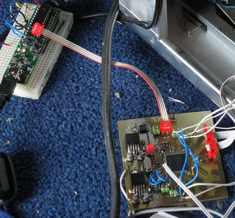
Above is a very early DSP prototype. In the top left hand corner can be seen the microstick plugged into a bread-board with a micromatch cable connecting it to the DSP. Very high tech, but it worked and was enough to show that this whole project was actually going to be possible.
I had the multichannel volume control and now the DSP up and running. My fear and trepidation towards software controlled silicon be gone!
The only thing really left to do was create a multichannel DAC and then put everything together. DACs were something I was quite familiar with so I didn't think it would be much of a problem, but when it came down to it, it was. Originally I had chosen to go with TIs PCM1792. This should have been simple but I could not get it to give the kind of measured performance that it should. 15+ different attempts at the PCB and conversations with TI resulted in zero success, the problem still remained. Giving up before solving this kind of problem isn't at all satisfactory but at some point you do have to stop. I figured it would make sense to try out another DAC chip and see if that would give me what I was after.
ESS techs range of DACs had always been intriging but I'd been put off by the clandestine mode of operations that the company seems to adhere to. Why no easy access to datasheets ESS tech? And why not use standard methods of distribution like everyone else does? Getting information, and simply buying the chips, hadn't been straight forward, but eventually a supplier was found. One PCB later and I had data sheet performance from the ES9018. Quite why the PCM1792 refused to work as intended I still, to this day, do not know.
After the ES9018 comes the aforementioned CS3318, a pair of them in fact, giving 16 output channels. These are then buffered by TIs awesome OPA1622 dual opamp. A little more troublesome to solder than your typical opamp package but well worth it. These come with the abilty to drive headphones, or act as a line driver without the need for the typical series connected output resistor. Naturally these are stable driving capacitive loads and capable of delivering a healthy amount of output current with vanishingly low levels of distortion. They also have an enable function that shuts down the part without creating a transient mess on it's output.
When driving loudspeakers the ES9018 works as an 8 channel part, performing conversion for each driver of my main system plus two channels for sub woofers. Then a pair of PCM51xx chips are used to provide an additional 4 channels for surround duty. Although not spec'd like the best, the PCM51/52 series of DACs are wonderful chips. They require a minimal amount of supporting components and take up very little space. Not to mention they come in a variety of flavours that now contain their own miniDSP cores. Flexible, inexpensive and easy to implement, what more could you ask for? Especially in this case where their requirements for a minimal amount of board space was very important.
When not driving loudspeakers the DSP functions are bypassed and the ES9018 is programmed to operate 4 channels in balanced configuration. Effectively two channels produce a normal polarity version of the left and right channels and two other channels do the same but with their polarities flipped. The four outputs are then fed into, a third, CS3318 chip which is then followed by an OPA1622. This then connects to the headphone socket on the front of the chassis.
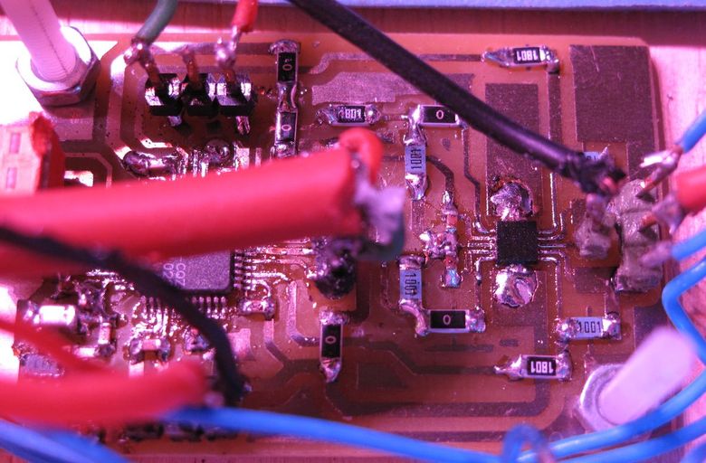
Above is a picture of the output board that drives the headphones and below a picture of the DSP board.
As can be seen, ton's of uFL connectors!
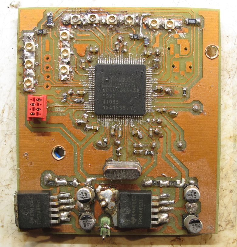
During the process of writing this up Analog Devices went off and released a new line of DSP chips. The ADAU146x series. Up until this point every additional chip into the sigmaDSP range had been limted in the number of input and output channels. Some came with superior processing power but, without enough channels, they were useless to me. So when this range was reelased I jumped on them and built up a board.
Below you can see the, mostly soldered, PCB. So out with the old (the above picture) and in with the new!
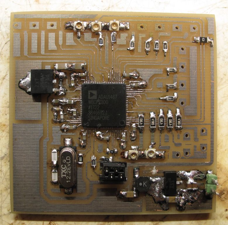
The ADAU1467 DSP core runs at twice the speed of the ADAU1445, so allows for considerably more flexibility. It also accepts 32 bit data and then processes that data at a native bit depth of 32 bits. When running double precision computation it doubles this up to 64 bit. By comparison the 1445 only accepts 24 bit data with 48 bits for double precision. This may not seem like much, but for some things it comes in handy.
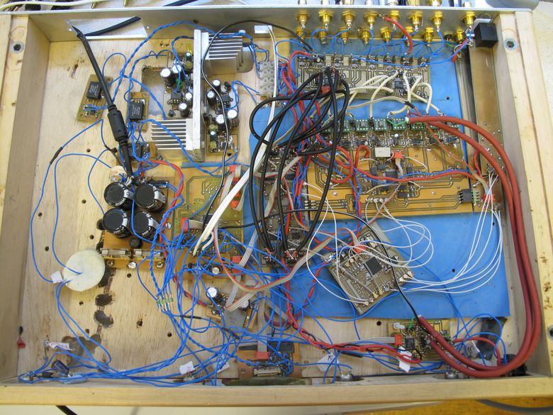
Above can be seen the inside of the entire DSP unit, along with the myriad of holes drilled in the bottom as changes were made to the design.
Main power is supplied by a laptop brick. This provides just under +20 volts and is fed into three switching regulator modules from Linear Technology. Power used to be provided by a small toroidal transformer, but using the laptop brick provides complete freedom from the mains earth and potential ground loops. The switching regulator modules have been designed specifically to keep radiated and conducted emissions down so are quite suitable for the given application. These act as pre-regulators for improved efficiency. One outputs +5V for the digital stuff one provides the positive rail for the analogue sections and the last one acts as an inverter, creating a negative rail for the analogue sections.
Linear regulators follow, using low noise surface mount designs, for the digital sections and two super regulators for the analogue stuff.
The three regulator modules can be seen to the top left, followed by the super regulators to their right. Further over to the right, under the phono connectors, is the 16 channel volume control and OPA1622 output buffers. Below the output board are the DACs. The larger of the two boards is the ES9018 and to the left of it the 4 PCM514x chips (the board with all the black wires). To the left of the 514xs is the main microprocessor board. This is used to control everything and program the DSP. On the far right are the LVDS receivers.
At the front of the case is the small PCB used to drive and power the OLED screen.
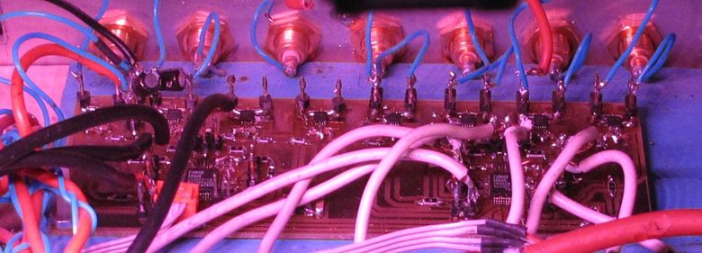
Below can be seen the output board with the 2 CS3318s and the line of OPA1622s.
The LVDS receivers have been used to allow the tramission of I2S down network cables. Currently the digital input is provided by an ASUS Xonar Essence ST card. This is the one with the expansion socket on the back and provides all the relevant signal/clock lines for 7.1 surround sound. Trying out an asynchronous, multichannel, USB > I2S device has been on my to-do list, but it's not very high up.
Main power is supplied by a laptop brick. This provides just under +20 volts and is fed into three switching regulator modules from Linear Technology. Power used to be provided by a small toroidal transformer, but using the laptop brick provides complete freedom from the mains earth and potential ground loops. The switching regulator modules have been designed specifically to keep radiated and conducted emissions down so are quite suitable for the given application. These act as pre-regulators for improved efficiency. One outputs +5V for the digital stuff one provides the positive rail for the analogue sections and the last one acts as an inverter, creating a negative rail for the analogue sections.
Linear regulators follow, using low noise surface mount designs, for the digital sections and two super regulators for the analogue stuff.
The three regulator modules can be seen to the top left, followed by the super regulators to their right. Further over to the right, under the phono connectors, is the 16 channel volume control and OPA1622 output buffers. Below the output board are the DACs. The larger of the two boards is the ES9018 and to the left of it the 4 PCM514x chips (the board with all the black wires). To the left of the 514xs is the main microprocessor board. This is used to control everything and program the DSP. On the far right are the LVDS receivers.
At the front of the case is the small PCB used to drive and power the OLED screen.
Below can be seen the output board with the 2 CS3318s and the line of OPA1622s.
The LVDS receivers have been used to allow the tramission of I2S down network cables. Currently the digital input is provided by an ASUS Xonar Essence ST card. This is the one with the expansion socket on the back and provides all the relevant signal/clock lines for 7.1 surround sound. Trying out an asynchronous, multichannel, USB > I2S device has been on my to-do list, but it's not very high up.
There are a couple of areas where things could be improved, but this unit is largely done. There are a couple of interesting DAC parts that have since been released that could potentially offer a replacement. The obvious upgrade would be to change out the ES9018 for one of the newer pro versions of ESS techs DACs. From what I can see they may even be pin compatible so a direct swap could be possible. Besides this ESS tech have added a part that includes an on-board charge pump, head-phone driver and similar performance to the ES9018, all inside one chip whilst requiring minimal supporting components. Cirrus Logic have also come up with a similar part, so a replacement for the PCM DAC chips could be around the corner!