Pre-amplifier/DSP/ADC Mk II
This project builds heavily upon the first iteration and has been in active use for a few years now. I felt it about time I updated the website to reflect this.
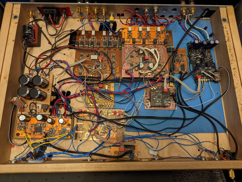
The devices basic functionality has remained, largely, unchanged. It's primary function is to accept digital audio data, perform digital signal processing on said data, and then convert the digital data into various analogue signals for amplification.
Data acquisition:
Where the digital data comes from has been upgraded and is now done via a USB interface using the CMedia CM6632A chip. This has been discussed in the headphone amplifier project along with the main pitfall of said chip. The CM6632A is prone to very high levels of random jitter and it adds this jitter to any of the master clocks that it outputs. This most likely comes from the noisy environment within the chip but it is highly destructive to the overall performance of any converter connected to it. With ADC/DACs of average quality this isn't a particularly big problem but when you're working with something better it severely affects the signal to noise ratio.
As the CM6632A acts asynchronously the data it outputs is slaved to the master clocks that are connected to it. The chip itself requiring two high quality oscillators to function. One is based around the 44.1kHz sample rate standard (and it's multiples) and one is based around the 48kHz sample rate standard and multiples. The CM6632A takes these two master clocks and then performs any necessary clock division on them and buffers them. These buffered clocks are then sent to output pins to be interfaced with suitable converters. Somewhere during the buffering process is where the random jitter is added to the clock lines. As all the buffered clocks are synchronous to the input master clocks it is possible to feed the master clocks directly into any audio converters and thus bypass the CM6632A altogether. This removes the added random jitter from the master clock line and corrects for the degraded noise floor present with the CM6632A alone.
Due to the number of converters used within this project I chose to use a CDCE18005 clock buffer, from TI, to provide the flexibility required. This device takes the outputs of the two CMOS master clocks and then buffers them to a variety of output formats with any necessary clock division. The CM6632A communicates, via I2C, with a micro controller and updates the micro with all information regarding the current sample rates. The micro controller then communicates with the CDCE18005 so that it can configure the master clocks correctly for the sample rates and connected audio converters.
Having to go to all this trouble is a massive headache and is reason alone not to use this series of USB>I2S interface. CMedia have now released updated products but those aren't readily available to DIYers. Whether or not they fix this problem I do not know.
The DACs:
When AKM released their AK4499 chip I was very excited to try it out. Here was something without an ESS hump, without their on-board re-sampling, and was also multichannel. Sadly each chip only came with 4 channels and I needed 8, so I would require 2 of them. The aforementioned problem, with the random CM6632A clock jitter, had me chasing ghosts that I thought were the AK4499 under performing. I was getting extremely low distortion but the noise floor was terrible. After I had isolated, and corrected for, the clock jitter the rest of the design fell into place. With distortion figures this low it was absolutely necessary to use an active notch, for testing, otherwise everything was garbage.
These are very high performance DACs and it's a shame that the factory fire at AKM brought this produts life to a close.
2x AK4499 were used for the main 8 channels and I then chose to use the ES9018, from the previous project, for the 8 additional channels, for the multiple subs and surround channels. The CS3318s were completely removed with all attenuation now being performed in the digital domain onboard the AK4499s and ES9018s.
The ADCs:
Before ESS had released their current line of ADCs there was really only one other manufacturer with products suitable for very high performance, especially, where measurements were concerned. This was AKM with their, now obsolete, AK5394A. A bit of an unusual chip in that its actual measured performance was capable of significantly outperforming its datasheet specification. It wasn't the quietest of chips around, and had high power consumption, but if you wanted the ability to measure low distortion, at close to 0dBfs, this was the chip to go for. It also didn't suffer from the noise shaping issues that most other ADCs had at higher sampling frequencies. Sadly I never managed to get my hands on any and had to try my luck with the AK5578 and AK5397.
The AK5397 was really supposed to be the successor to the AK5394A but it had one problem and that was high distortion. Try as I might there was nothing I could do to get around this. The chip had low noise and a low noise floor, all the way to 100kHz, but the distortion was terrible. The AK5578, in stereo mode, had lower distortion, low noise, but didn't have a flat noise floor. None of the typical manufacturers had a product that was any better either so you were really stuck.
Then along came ESS with their ES9822PRO and this was released at a time when it was sorely needed. Very low noise, very low distortion, low power, on-board THD compensation processing, easy to use, and inexpensive! What more could you ask? Well I signed an NDA and got preliminary access to the datasheets and chips. ESS are known for having poor datasheets and their preliminary ones are even worse but I finally got the ADCs doing what they should. These are fantastic products. One of their big advantages, as least as far as I could tell, is that their analogue inputs do not connect directly with the ADCs sampling circuitry. This is usually how things are done and as a result there are requirements for certain amounts of input capacitance so an ADC can work correctly. As anyone will tell you driving this capacitance is not an easy task and is an easy way of degrading the distortion performance of your input buffer. The ES9822PRO already has internal circuitry driving the sampling section and as a result all your input buffer has to do is drive the devices input impedance. Yes you need to ensure your buffer has adequate low-pass filtering but it no longer needs to drive large amounts of capacitance, as with something like the AK5397.
I decided to use two of these in dual mono configuration for the best noise performance.
Power supplies:
The previous project had used a bunch of LDOs, along with Super regulators for the op-amps, and then some switching regulator modules to carry the heavy lifting plus to create a negative rail. The switching regulators, and inverter, were mandatory and along with a double insulated main SMPS eliminated ground loops and any mains hum. Begone transformers.
For this version I wanted to redo all the power supplies and make things less complicated. This time round all the individual PCBs would carry their own LDOs, for powering all the onboard circuitry, so that the Super regulators wouldn't be needed.
Power sensitive areas are powered by LT3045s, LT3094s and LP5907s. Truth be told I think the only power supplies where this really mattered were the ADCs/DACs analogue circuitry and then the oscillators and clock buffers. All of the op-amps would have been fine with something much more basic. In fact the op-amps would probably have been fine being powered directly by the switching regulators.
I did try experimenting with more basic LDOs on the DAC and ADC supplies but this affected their performance, don't skimp! Initially I had also used PCB traces to route the power to the 4 separate DAC channels in the AK4499s. Keeping in mind here that I am only using 2 layer boards so I didn't have the luxury of low impedance power plains. Nevertheless a single LT3045 routed, via meandering traces, to all 4 channels was not a good match for performance. This was somewhat surprising considering that the power pins were filtered via the AKM recommended RC filters but clearly the DAC wasn't happy. At first I thought I was going to need a regulator per channel but this wasn't necessary. Instead of using traces I tried soldering a chunky wire directly from the output of the regulator to each DAC channel. Problem solved!
For the switchers I chose to move away from the Linear Technology modules because their BGA footprint was not great for DIY. I'd had intermittent connection issues with one of them that was not acceptable. This time I used LMR33620s, to generate the positive rails, and a LMZ34002 to generate the negative rail, both from TI.